– 2 –
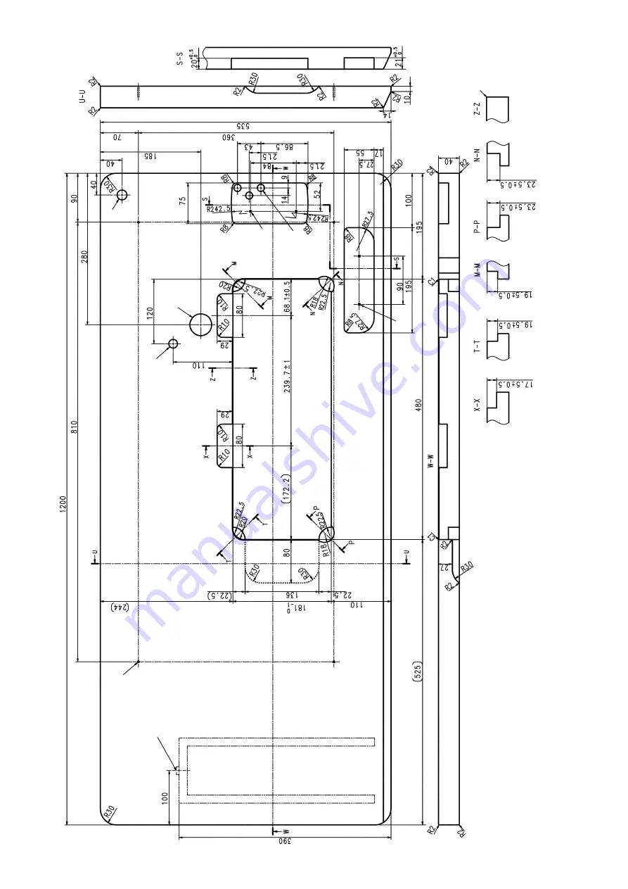
DRAWING OF TABLE
A
B
C
D
E
F
H
G
I
A
4
xø3.4
on the
bottom surface, depth 20
(Drill a hole at the time of set-up.)
B
Installing position of drawer stopper (on the reverse side)
C
ø18 drilled hole
D
3
xø13 drilled hole
E
2
xø3.5, depth 10
F
2
xø3.5, depth 10
G
ø40
±0.5
drilled hole
H
ø16
depth 30
I
C1.5 to C2.5
(hinge side only)
Содержание DDL-8100B-7 Series
Страница 1: ...I DDL 8700B 7 INSTRUCTION MANUAL ...


