Johnson Controls TL-MAP1810- OPM Скачать руководство пользователя страница 17

updates using the USB port. When the MAP Gateway is connected and powered from the USB port,

FC/SA bus functions are not available.

Note: 

The USB connection on the MAP Gateway is not designed for constant use. The USB port

should be used only when needed.

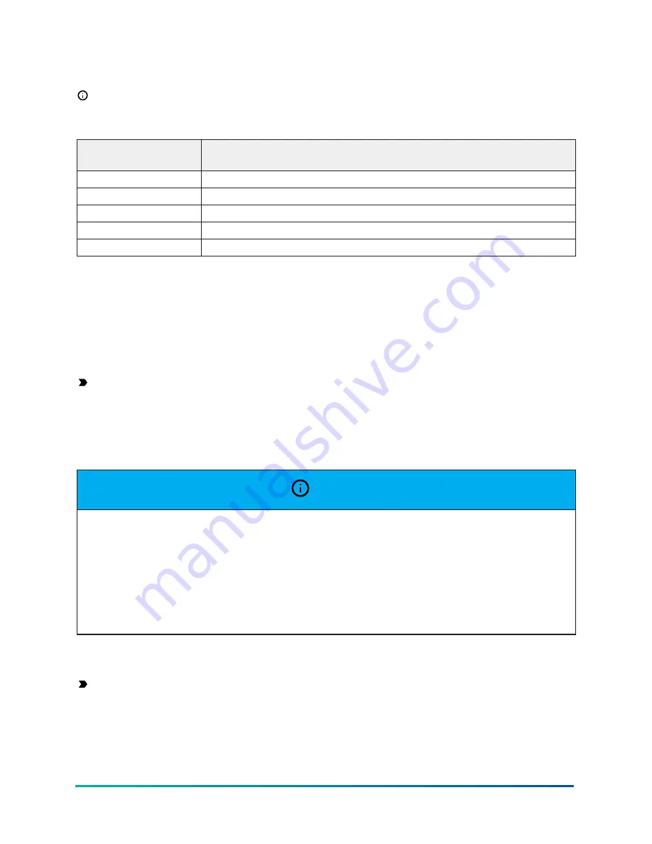
Table 1: USB Port Pin Designations

Pin Number (Both

Ends of Cable)

Signal Name

1

+5 VDC

2

Data -

3

Data +

4

No Connection

5

Ground

Ethernet Port

The Ethernet port on the MAP Gateway is an 8-pin RJ-45 jack. The maximum allowable cable length

is 100 m (328 ft).

External Power Supply Connections

Important: 

If you install the SC-AP Gateway inside an outdoor chiller, you must use the SC-

Equip card for power.

To connect the MAP Gateway using the supplied external power source:

1.  Connect the 15 VDC output connector of the power supply to the power supply port of the

MAP Gateway.

 NOTICE

Risk of Property Damage.

Do not apply power to the system before checking all wiring connections. Short circuited or improperly

connected wires may result in permanent damage to the equipment.

Risque de dégâts matériels.

Ne pas mettre le système sous tension avant d'avoir vérifié tous les raccords de câblage. Des fils

formant un court-circuit ou connectés de façon incorrecte risquent d'endommager irrémédiablement

l'équipement.

2.  Connect the power supply to the supplied power cord.
3.  Plug the power cord into a 100 to 240 VAC outlet.

Important: 

 Power should only be applied and removed by connecting and disconnecting

the power cord from the 100–240 VAC outlet. Applying or removing power by connecting or

disconnecting the 15 VDC connector can damage the unit.

17

Mobile Access Portal Gateway Installation Guide

Содержание TL-MAP1810- OPM

Страница 1: ...P TL MAP1810 OPE TL MAP1810 OPA TL MAP1810 OPM TL MAP1810 OPS TL MAP1810 OPI TL MAP1810 OSx Building Technologies Solutions www johnsoncontrols com 2021 01 22 24107378J Mobile Access Portal Gateway In...

Страница 2: ...2 Mobile Access Portal Gateway Installation Guide...

Страница 3: ...Field Bus Communications Connections 16 USB Port 16 Ethernet Port 17 External Power Supply Connections 17 Operation 18 Accessing Smart Equipment Using the MAP Gateway 18 Connecting to the MAP Gateway...

Страница 4: ...4 Mobile Access Portal Gateway Installation Guide...

Страница 5: ...UCBs The MAP Gateway also supports the TEC3000 Series Thermostats The wireless connection on the MAP Gateway facilitates a supported mobile device to be up to 30 m 100 ft line of sight away indoors a...

Страница 6: ...ce received including interference that may cause undesired operation Warning Part 15 21 Changes or modifications not expressly approved by the party responsible for compliance could void the user s a...

Страница 7: ...unting bracket locking screw requires a T15 Torx screwdriver Portable Use When used as a portable unit the MAP Gateway should be housed in the supplied shell During use the unit can be temporarily hun...

Страница 8: ...nd the MAP Gateway Use line of sight if possible Metal objects such as cabinet doors enclosures and pipes and concrete objects such as pillars walls and ceilings may limit Wi Fi service To accommodate...

Страница 9: ...hich puts the labels upside down Location Considerations Observe the following guidelines when mounting the MAP Gateway Mount the MAP Gateway in areas free of corrosive vapors and observe the environm...

Страница 10: ...facing down is not recommended Although the bracket has two mounting clips only the bottom clip snaps inward The top clip is permanently locked in the outward position and it can be used as an additio...

Страница 11: ...he bracket so that the back of the unit is flush with the mounting surface using the screw holes on the side of the bracket or using the holes in the DIN rail clips This orientation helps accommodate...

Страница 12: ...outward to the extended position 2 Mark mounting hole locations on the wall using the dimensions shown in Figure 7 Figure 8 or Figure 9 or hold the bracket against the wall and mark the hole location...

Страница 13: ...Figure 7 Mounting Holes Flat Mounting Note The screw holes on the MAP Gateway can accommodate M3 5 and 6 screws 13 Mobile Access Portal Gateway Installation Guide...

Страница 14: ...Figure 8 Mounting Holes Side Mounting Note The screw holes on the MAP Gateway can accommodate M3 5 and 6 screws Mobile Access Portal Gateway Installation Guide 14...

Страница 15: ...hors for each hole if necessary 4 Hold the bracket in place insert the screws through the mounting clips and into the screw holes and then carefully tighten all screws Important Do not overtighten the...

Страница 16: ...o connect the MAP Gateway to the SA FC field bus for communication connect one end of the RJ 12 cable to the MAP Gateway and the other end of the cable to a controller or network sensor Note The MAP G...

Страница 17: ...Connect the 15 VDC output connector of the power supply to the power supply port of the MAP Gateway NOTICE Risk of Property Damage Do not apply power to the system before checking all wiring connecti...

Страница 18: ...t Equipment Using the MAP Gateway When the MAP Gateway is physically connected to an MS TP network users can have access to Smart Equipment devices The MAP Gateway can connect through the SA bus or th...

Страница 19: ...P Gateway directly to the field bus To interact with a device or product on the network to view devices setpoints or view alarms users select the device using a web enabled device that is connected to...

Страница 20: ...t is trusted in a browser If you wish to install your own certificate refer to Adding a Private Key and Certificate to MAP Gateway in the Mobile Access Portal Gateway Network and IT Guidance Technical...

Страница 21: ...Important To use a unit that is reset to factory defaults you must have the default login information supplied in the Quick Start Guide that shipped with the unit This includes the factory SSID and pa...

Страница 22: ...Figure 14 Using the Reset Button Mobile Access Portal Gateway Installation Guide 22...

Страница 23: ...ess and hold the reset button for 6 seconds The Fault LED displays Slow Flicker behavior at first then Fast Flicker behavior 2 Release the reset button within 3 seconds of the change to Fast Flicker T...

Страница 24: ...n Steady Transmitting data Flicker Data is being transmitted on the network Ethernet Green On Steady Off Communication not established On Steady Communication established Flicker Data transmission Wi...

Страница 25: ...eway fails to operate within its specifications replace it The MAP Gateway is not a serviceable product however it does support software updates to enable feature enhancements For a replacement unit s...

Страница 26: ...the certificate Note You must time sync the device if the local time on SC Equip data does not match the correct local time Do this in the BACnet time sync menu The time on the browser device is then...

Страница 27: ...nd lanyard MP STAKIT 0 Stationary Cradle Only Includes mounting bracket and field bus adapter MP STAKIT 0Hx Stationary Cradle Kit Includes mounting bracket field bus adapter and 100 240 VAC line volta...

Страница 28: ...22 to 140 F Non Operating 40 to 70 C 40 to 158 F Ambient Humidity Conditions Storage 40 to 70 C 40 to 158 F 5 to 95 RH 30 C 86 F maximum dew point conditions Operating 0 50 C 32 to 122 F 5 to 95 RH 3...

Страница 29: ...mm 4 23 32 x 2 3 4 x 31 32 in when used vertically Unit in shell 128 x 75 x 29 5 mm 5 1 32 x 2 61 64 x 1 5 32 in when used vertically Housing White Acrylonitrile butadiene styrene ABS bracket plenum...

Страница 30: ...Environmental Air Space in Accordance with Section 300 22 C of the National Electric Code Transmission Complies with FCC Part 15 247 Regulations for Low Power Unlicensed Transmitters Transmitter FCC I...

Страница 31: ...the antenna or antennas and the user should not be less than 20 cm ANATEL 03298 17 06174 Para consultas visite www anatel gov br Argentina CNC N mero de Inscripci n C 17791 Jamaica This product has be...

Страница 32: ...5143 ESSEN GERMANY JOHNSON CONTROLS 507 E MICHIGAN ST MILWAUKEE WI 53202 USA Contact information Contact your local branch office www johnsoncontrols com locations Contact Johnson Controls www johnson...

Отзывы: