RXB PLUS ROTARY SCREW COMPRESSOR UNITS
INSTALLATION
070.101-IOM (JAN 13)
Page 11
the.chamber.provided.on.the.oil.outlet.connection..Determine.
the.size.of.the.water-cooled.oil.cooler.supplied.with.the.unit,.
then.refer.to.table.for.the.water.connec.tion.size.and.water.
flow.range.(GPM)..
The water supply must be sufficient to
meet the required flow.
It.is.imperative.that.the.condition.of.cooling.water.and.closed.
loop. fluids. be. analyzed. and. maintained. regularly. and. as.
necessary.to.prevent.corrosion.of.heat.exchanger.surfaces...
The.oxygen.content.of.river.water.and.some.other.cooling.
water.sources.will.oxidize.steel.tubes.and.cause.premature.
failure..Careful.attention.to.water.treatment.is.essential.to.
ensure.adequate.life.of.steel.cooler.tubes.if.cooling.tower.
water.is.used..The.condition.of.heat.exchanger.tubes.should.
be.checked.semiannually.to.prevent.hazard.
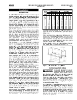
OIL COOLER DATA TABLE
SIZE - Inches
APPROX
WATER FLOW
RANGE (GPM)
...
COOLER
WATER CONN
5.Foot.Lengths
6".DIA.
1..NPT
10.–.23
8".DIA.
1-1/4..NPT
35.–.60
NOTE: The water regulating valve shipped with the unit
will be sized to the specific flow for the unit.
THERMOSYPHON OIL COOLING (OPTIONAL)
Thermosyphon.oil.cooling.is.an.economical,.effective.method.
for. cooling. oil. on. screw. compressor. units..Ther.mosyphon.
cooling.utilizes.liquid.refrigerant.at.condenser.pressure.and.
temperature.which.is.partially.vaporized.at.the.condenser.
temperature.in.a.shell.and.tube-.or.plate-type.vessel.cool-
ing.the.oil.to.within.15°F.of.that.temperature..The.vapor,.at.
condensing.pressure,.is.vented.to.the.condenser.inlet.and.
reliquified..This.method.is.the.most.cost.effective.of.all.cur-
rently.applied.cooling.systems.since.no.compres.sor.capacity.
is.lost.or.compressor.power.penalties.in.curred..The.vapor.
from.the.cooler.need.only.be.con.densed,.not.compressed..
Refrigerant.flow.to.the..cooler.is.automatic,.driven.by.the.
thermosyphon.principle,.and.cooling.flow.increases.as.the.
oil.inlet.temperature.rises.
EQUIPMENT
. -.The. basic. equipment. required. for. a. ther-
mosyphon.system.consists.of:
1.
.A.source.of.liquid.refrigerant.at.condensing.pressure.and.
temperature.located.in.close.proximity.to.the.unit.to.mini.mize.
piping.pressure.drop..The.liquid.level.in.the.refrigerant.source.
must.be.6.to.8.feet.above.the.center.of.the.oil.cooler.
2.
.A.shell.and.tube-.or.plate-type.oil.cooler.with.a.300.psi.
minimum.design.working.pressure.on.both.the.oil.and.re-
frigerant.sides.
Due.to.the.many.variations.in.refrigeration.system.design.
and.physical.layout,.several.systems.for.ensuring.the.above.
criteria.are.possible.
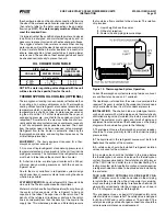
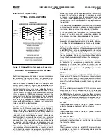
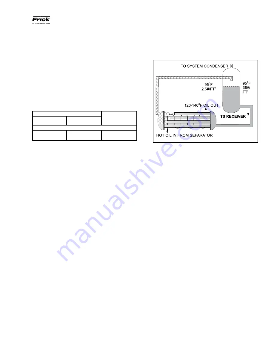
SYSTEM OPERATION
.-.Liquid.refrigerant.fills.the.cooler.tube.
side.up.to.the.Thermosyphon.receiver.liquid.level.
Water.or.hot.oil.(above.the.liquid.temperature).flowing.through.
the. cooler. will. cause. some. of. the. refrigerant. to. boil. and.
vaporize.in.the.tubes..The.vapor.rises.in.the.return.line..The.
density.of.the.refrigerant.liquid/vapor.mixture.in.the.return.
line.is.considerably.less.than.the.density.of.the.liquid.in.the.
supply.line..This.imbalance.provides.a.differential.pressure.
that.sustains.a.flow.condi.tion.to.the.oil.cooler..This.relation-
ship.involves:
1.
.Liquid.height.above.the.cooler.
.
2.
.Oil.heat.of.rejection.
.
3.
.Cooler.size.and.piping.pressure.drops.
Figure 13 - Thermosyphon System Operation
Current.thermosyphon.systems.are.using.two-pass.oil.cool-
ers.and.flow.rates.based.on.4:1.overfeed.
The.liquid/vapor.returned.from.the.cooler.is.separated.in.the.
receiver..The.vapor.is.vented.to.the.condenser.inlet.and.need.
only.be.reliquified.since.it.is.still.at.condenser.pressure.
INSTALLATION
.-.The.shell.and.tube-.or.plate-type.thermo-
syphon.oil.cooler.with.oil-side.piping.and.a.thermostatically.
controlled.mixing.valve.(if.ordered).are.factory.mount.ed.and.
piped..The.customer.must.supply.and.install.all.piping.and.
equip.ment.located.outside.of.the.shaded.area.on.the.piping.
diagram.with.consideration.given.to.the.following:
1.
.The.refrigerant.source,.thermosyphon.or.system.receiv.er,.
should.be.in.close.proximity.to.the.unit.to.minimize.piping.
pressure.drop.
2.
.The.liquid.level.in.the.refrigerant.source.must.be.
6
.to.
8
.
feet
.above.the.center.of.the.oil.cooler.
3.
.A.safety.valve.should.be.installed.if.refrigerant.isolation.
valves.are.used.for.the.oil.cooler.
4.
An.angle.valve.should.be.installed.in.the.piping.before.
the.thermosyphon.oil.cooler.to.balance.the.thermosyphon.
system..Also.recommended.is.the.installation.of.sight.glasses.
at.the.TSOC.inlet.and.outlet.to.aid.in.troubleshooting..The.
factory-mounted,.plate-type.thermosyphon.oil.cooler.requires.
a.refrigerant-side.drain.valve.to.be.provided.and.installed.by.
the.customer.
TSOC AND WCOC OPTIONAL OIL SIDE SAFETY RE-
LIEF -
Compressor.units,.which.have.valves.in.the.oil.piping.
to.isolate.the.oil.cooler.from.the.oil.separator.for.servicing,.
may.have.factory.installed.piping.to.relieve.the.shell.side.(oil.
side).safety.valve.directly.into.the.oil.separator,.as.shown.in.
the.P.&.I.diagrams.on.pages.58.through.60.
This.arrangement.uses.a.special.UV.stamped.safety.valve.
rated.for.liquid.and.vapor.relief..The.safety.valve.is.designed.
for.500.psi.DWP.and.is.set.to.relieve.at.75.psi.delta.P..The.
safety.valve.piping.contains.flanged.connections.should.the.
valve.require.maintenance.or.replacement.
Содержание Frick RXB Plus 12
Страница 65: ...RXB PLUS ROTARY SCREW COMPRESSOR UNITS MAINTENANCE 070 101 IOM JAN 13 Page 65 OPERATING LOG SHEET ...
Страница 66: ......
Страница 67: ......


