background image

9

 -

Introduction


This section details all of the available 

capabilities in the CMS-1655, and should be 

used to access more detailed information 

regarding the menu options in the product 

organized as follows:

•  Overview
•  Main Setup Menu
•  Unit Setup
•  System Setup
•  Display Setup
•  Diagnostics 

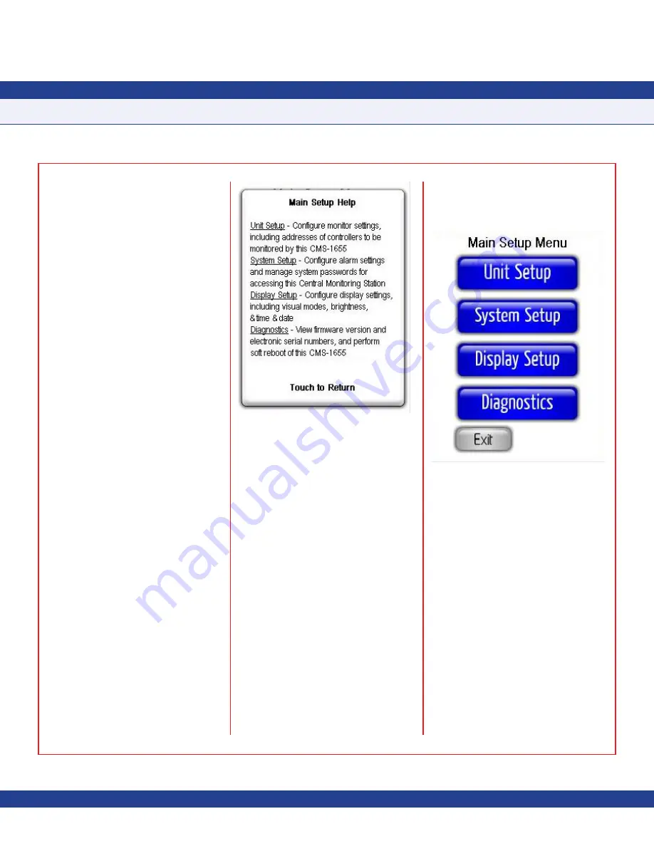
The touchscreen user interface of the CMS-

1655 Central Monitoring Station is designed 

to facilitate the initial setup and configuration, 

diagnosis, and troubleshooting during the 

installation process. Each menu screen is 

limited to four options, thereby simplifying 

navigation through the menu system. Context-

sensitive help is available at most menu 

screens and is accessed simply by touching 

the menu title on any particular screen (see 

Figure 12

).

To exit from any

 Help

 screen, simply touch the 

display anywhere. Multi-page menu screens 

have navigation buttons at the bottom of each 

screen that allow the user to move forward 

or backward, and include a convenient 

Exit


button on the last screen to quickly exit the 

menu system and return to the main display.

To preserve the security of the configuration 

settings, up to 10 passwords may be 

programmed to prevent unauthorized access 

to the system configuration settings. To further 

prevent unauthorized access, the


CMS-1655 

user menu system incorporates automatic 

time-out periods based on the screen 

currently being displayed.

Menu screens time-out after 90 seconds 

of inactivity, while configuration screens 

automatically time-out after 60 seconds. 

This prevents unauthorized access to the user 

menu system should a unit be inadvertently 

left unattended at one of the configuration 

screens.

Main Setup Menu

All of the configuration screens that allow the 

settings of the CMS-1655 to be configured for 

a specific application originate from the top 

level of the user interface menu system, the 

Main Setup Menu

 as shown in 

Figure 13

The 

Main Setup Menu

 includes four options 

which provide support for 1) configuring 

the settings specific to the unit as a central 

monitoring station, 2) configuring the alarm 

facility settings and managing the system 

security passwords, 3) configuring the display-

specific settings, and 4) using the diagnostics 

and troubleshooting resources.

The majority of the configuration settings 

are available through the 

Unit Setup


option on the 

Main Setup Menu

. Options 

available through the 

System Setup Menu


option include support for configuring the 

comprehensive alarm facility and managing 

the security passwords. The 

Display Setup 

option provides support for configuring all of 

the display-specific settings integrated in the 

CMS-1655. 

The CMS-1655 can simultaneously display 

in real-time up to four monitored parameters, 

their operating modes (if applicable), alarm 

status, and their associated names. The 

Diagnostics

 menu option provides information 

specific to this particular CMS-1655 unit.

PROGRAMMING MANUAL

Fig. 12 Main Setup Help

Fig. 13 Main Setup Menu

Содержание CMS-1655

Страница 1: ...ore beginning installation North American Emissions Compliance United States Canada Installation This Class A digital apparatus meets all the requirements of the Canadian Interference Causing Equipmen...

Страница 2: ...655 to Nearest JCI Controller 7 Notes 8 PROGRAMMING MANUAL Introduction 9 Main Setup Menu 9 Unit Setup 10 Configuring Monitor Settings 10 Configuring Audible Alert Settings 11 System Setup 12 Configur...

Страница 3: ...5 or by separate power supply 18 to 32 Vdc Touchscreen User Interface LCDSizeandType 3 2 diagonal transmissive Resolution 240 pixels x 320 pixels portrait mode Viewing Area 50 60 mm x 66 80 mm Color D...

Страница 4: ...parameter is within defined normal operating limits Yellow indicates that the monitored parameter has drifted outside of the normal operating limits and is approaching the alarm region Red indicates t...

Страница 5: ...tainless steel faceplate of the CMS 1655 Run the 4 conductor dual twisted pair electrical connection from the nearest FMS 1650 55 or HMS 1650 55 Refer to the wiring diagram shown on page 7 for details...

Страница 6: ...wn on page 7 for details 6 Terminate the interface cable originating from the host controller at the 4 position and 3 position terminal blocks on the back side of the CMS 1655 display ensuring proper...

Страница 7: ...used to indicate that a door is open at a monitored FMS unit if a door switch has been incorporated with the FMS A red background with the red exclamation point action icon indicates that the monitor...

Страница 8: ...four parameters of up to four independent JCI controllers Once the individual controllers have been specified the parameters at each monitored controller may be selected This is accomplished by tappin...

Страница 9: ...tandard view is selected may be adjusted either by using the hotspots on the main display or by selecting Display Setup Set Time Date The CMS 1655 is also designed to request time and date settings pe...

Страница 10: ...N7 CN3 NETWK NETWK GND V FMS or HMS Backplane Connections Daisy chain together the SUB_NETs on the backplanes of all the FMS 1655 and or HMS 1655 units that will be monitored by the CMS 1655 Connect t...

Страница 11: ...improvement TRIATEK reserves the right to change product specifications without notice Due to continuous improvement JCI reserves the right to change product specifications without notice INSTALLATIO...

Страница 12: ...ed Menu screens time out after 90 seconds of inactivity while configuration screens automatically time out after 60 seconds This prevents unauthorized access to the user menu system should a unit be i...

Страница 13: ...e CMS 1655 Single Station Monitor should be selected if a single controller is being monitored If multiple parameters at a single station need to be monitored then the monitor mode should be specified...

Страница 14: ...lected After selecting the specific stations which should activate the audible alarm when the alarm status occurs pressing the Next button invokes the next configuration screen as shown in Figure 19 w...

Страница 15: ...e configuration settings associated with the CMS 1655 alarm facility may be accessed at the Alarms Setup menu shown in Figure 22 Options on this menu allow individual alarms to be enabled for each of...

Страница 16: ...missioned mode is selected at a monitored HMS 1650 55 These modes are indicated by an action icon represented as a red circle with a line through its center The Safety Halo status indicator if enabled...

Страница 17: ...ormal operating hours if Nightly Auto Dim is enabled or continuously otherwise To configure the Safety Halo feature to reduce in brightness intensity during evening hours or otherwise select the Night...

Страница 18: ...uld be entered as a two digit entry For convenience the time and date may also be entered directly from the main screen Single Station Monitor mode only by tapping the time and date fields respectivel...

Страница 19: ...een made to the network parameters subnetwork address Selecting this option invokes the warning message as shown in Figure 31 informing the user that the CMS 1655 will be reset when the OK button is t...

Страница 20: ...Due to continuous improvement JCI reserves the right to change product specifications without notice User Menu Flow Diagram 17 PROGRAMMING MANUAL...

Страница 21: ...The Next Generation in Critical Airflow Controls CMS 1655 Central Monitoring Station Installation and Programming Manual LB CMS1655 S LB CMS1655 T Code No LIT 12013121 Rev A Issued August 2018 Refer...

Отзывы: