8.0 ASSEMBLY INSTRUCTIONS
1. Adjusting Cable Tension: With the locking legs extended approximately 8
inches, tighten both the left and right side cable bolts equally. (See Figure
5). To check tension, grab cable in center and pull up on it with about 30
pounds of force. Cable should deflect about 1-3/4” to 2”. This would be the
proper cable tension. To adjust the cables for equal rise, measure exactly
the amount of locking leg that is extended. If for instance, the left side
locking leg is extended further than the right, loosen the right cable bolt
and tighten the left cable bolt. Continue this procedure until both locking
legs are extended equally. NOTE: When adjusting cables, hold the fitting
on the end of the cable with vice grips to prevent turning.
2. Attach the 1/2” O. D. hydraulic lines to the tee fitting provided so that it will
be next to the PVC through hull fitting (halfway between the pulleys). Tape
the open ends to prevent any foreign objects from entering during
installation. (See Figure 6).
12
Содержание 40HP210ES
Страница 9: ...Figure 1 Bay Layout Option A 8 ...
Страница 10: ...Figure 2 Bay Layout Option B 9 ...
Страница 12: ...Figure 4 Elevation 11 ...
Страница 14: ...Figure 5 Cable Routing 13 ...
Страница 15: ...Figure 6 Hydraulic and Air Connections 14 ...
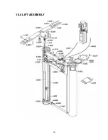
Страница 25: ...16 0 LIFT ASSEMBLY 24 ...
Страница 27: ...3 1026 1 Pump Stand Bolt Down Standard Not shown in figure 26 ...
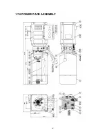
Страница 28: ...17 0 POWER PACK ASSEMBLY 27 ...
Страница 31: ...18 0 AVAILABLE ACCESSORIES Figure 10 Truck Height Extension Adapter Part No 3 1028 Set of 4 30 ...


