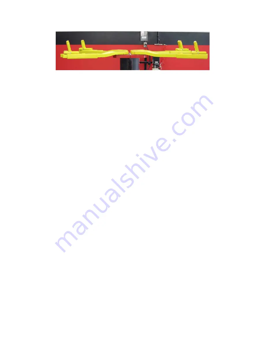
Figure 9 - INCORRECT positioning of flip pad adapters
Lifting:
1. Push in on “pump electrical switch” and raise lift until adapters contact
vehicle.
2. Check to make certain that all height adapters are making full and proper
contact and are stable.
3. Raise lift approximately 18” and check stability by rocking vehicle front to
rear.
4. While raising the lift, the air lift safety locks will engage at different stages.
Raise lift to desired height and lower onto lift locks. Avoid sporadic starting
and stopping of pump motor if possible.
5. To prevent pump motor damage, always lower load onto safety locks
when restarting motor in mid-stroke.
Lowering:
1. Make sure area under vehicle is clear of obstacles.
2. Raise lift slightly.
3. To disengage air-operated lift safety locks, push air lock release button in
while pushing on handle to lower the lift.
4. Lower the lift until lift superstructures make full contact with floor.
5. Rotate arms to provide tire clearance.
6. Make certain adapters are in the flat position before removing vehicle.
NOTE: Remove 8-7/8” Truck Height Adapters, if used.
20
Содержание 40HP210ES
Страница 9: ...Figure 1 Bay Layout Option A 8 ...
Страница 10: ...Figure 2 Bay Layout Option B 9 ...
Страница 12: ...Figure 4 Elevation 11 ...
Страница 14: ...Figure 5 Cable Routing 13 ...
Страница 15: ...Figure 6 Hydraulic and Air Connections 14 ...
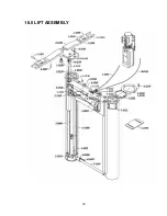
Страница 25: ...16 0 LIFT ASSEMBLY 24 ...
Страница 27: ...3 1026 1 Pump Stand Bolt Down Standard Not shown in figure 26 ...
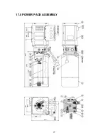
Страница 28: ...17 0 POWER PACK ASSEMBLY 27 ...
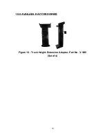
Страница 31: ...18 0 AVAILABLE ACCESSORIES Figure 10 Truck Height Extension Adapter Part No 3 1028 Set of 4 30 ...

