


9.1 POWER PACK INSTALLATION
1.
POWER UNIT REQUIREMENTS:
230 volts, single-phase power. Use
separate circuit for each unit and protect each unit with 30 AMP time delay
fuse or circuit breaker.
2. Have a certified electrician wire your pump to the pump motor. The
electrical diagram is provided. (See Figure 7).
3. Attach pumping unit (tank down) to location selected in front of lift. The
connecting fittings should be at least 36” off the floor.
4. Install the hydraulic lines and air lines through the 1-1/2” PVC.
5.
FILLING PUMPING UNIT:
Fill pumping unit with AW-32 hydraulic oil,
I.S.O. 32 with anti-rust and anti foam agents (approx. 14 quarts). DO NOT
USE TRANSMISSION FLUID.
9.2 HYDRALLIC AND AIR CONNECTIONS
1. Install the 1/2” O. D. x 21’ hydraulic line and the 1/4” O. D. x 21’ airline
from the pump to the pulley box through the 1-1/2” PVC sweep.
2. Connect the hydraulic line to the tee and the air line to the air cylinder
elbow fitting, both located inside the pulley box.
3. Connect the other ends to the pumping unit hydraulic fitting and air lift lock
release button (safety release valve) making sure that all fittings are
properly tightened. (See Figure 5).
4. Run an air supply line from shop air to the 1/8” pipe fitting at the base of
the air lock release button on pump.
16
Содержание 40HP210ES
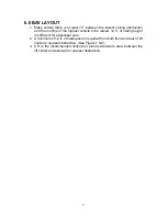
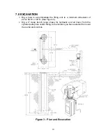
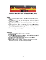
Страница 9: ...Figure 1 Bay Layout Option A 8 ...
Страница 10: ...Figure 2 Bay Layout Option B 9 ...
Страница 12: ...Figure 4 Elevation 11 ...
Страница 14: ...Figure 5 Cable Routing 13 ...
Страница 15: ...Figure 6 Hydraulic and Air Connections 14 ...
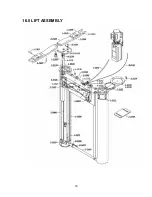
Страница 25: ...16 0 LIFT ASSEMBLY 24 ...
Страница 27: ...3 1026 1 Pump Stand Bolt Down Standard Not shown in figure 26 ...
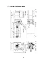
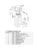
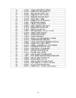
Страница 28: ...17 0 POWER PACK ASSEMBLY 27 ...
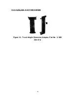
Страница 31: ...18 0 AVAILABLE ACCESSORIES Figure 10 Truck Height Extension Adapter Part No 3 1028 Set of 4 30 ...


