background image

    Models

Revision 03-2012

12

Toucan    1210
Toucan    1310

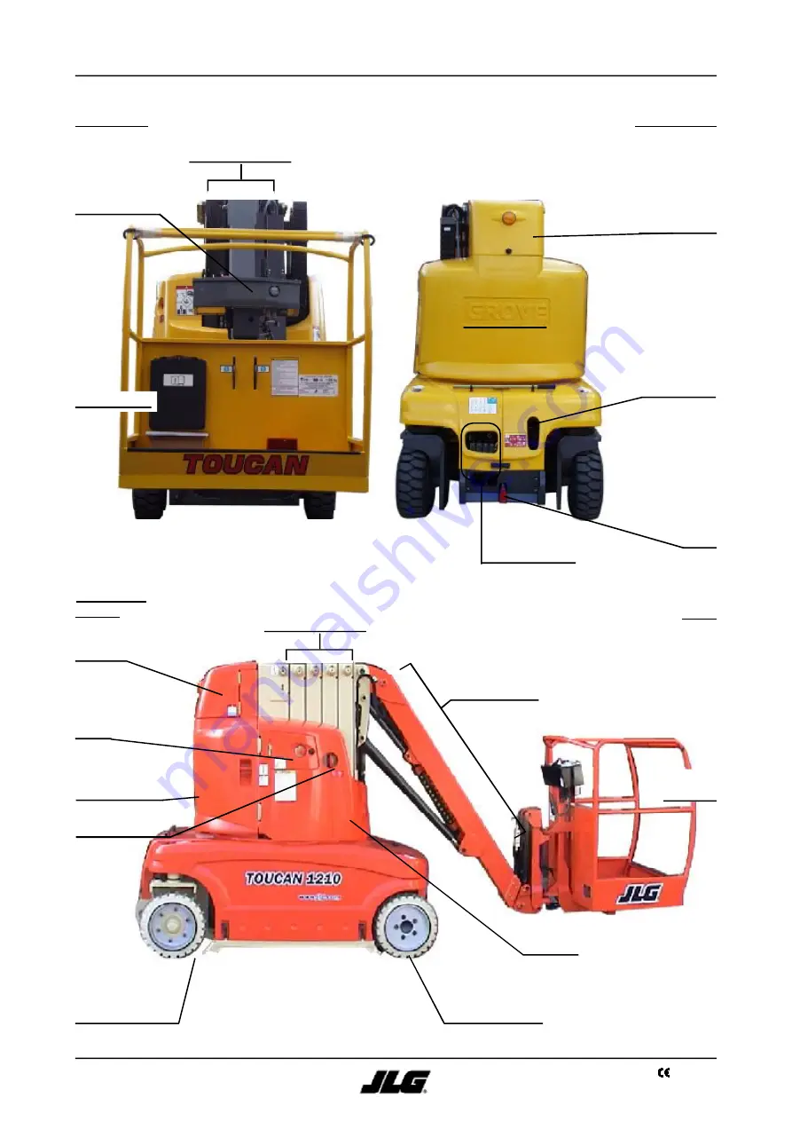
WORK PLATFORM CHARACTERISTICS

2

2

Steering wheels

FRONT VIEW

REAR

Hand pump

REAR VIEW

 Driving wheels

Counterweight

FRONT

VIEW LEFT

Counterweight

Telescopic mast

Emergency control
panel

Charger

Circuit breaker

Platform
control panel

Release

valve

Manual  box

Telescopic mast

Work

platform

Breakdown
control panel

Telescopic jib

Access to side
batteries

Access to the

front battery

Содержание TOUCAN 1210

Страница 1: ...717 485 6417 C E JLG Manufacturing Europe Breitwaterstraat 12A Oude Bunders 1034 B 3630 Maasmechelen Tel 32 0 89 774 974 Fax 32 0 89 777 427 FRANCE JLG France SAS Z I de Fauillet BP 20 47400 TONNEINS...

Страница 2: ......

Страница 3: ...3 Models Revision 03 2012 Toucan 1210 Toucan 1310 MA0295 04 Models English MACHINE SERIAL NUMBER Toucan1210 _____ Toucan1310 _____...

Страница 4: ...diverter 3 15 Cylinders supply manifold 3 16 Mast cylinder 3 16 1 Jib cylinder 3 16 2 Telescope cylinder 3 16 3 Assistance cylinder Master cylinder Slave cylinder 3 16 4 Rotation cylinder optional 3...

Страница 5: ...features Movement cut out 4 3 Adjustment of the battery discharge indicator 4 4 Speed electronic controller 4 5 Circuit breakers Fuses 4 6 Circuit breakers 4 6 1 Fuses 4 6 2 Resetable fuses Polyswitch...

Страница 6: ...alignment 7 6 Lifting chains adjustment 7 7 Verification and lubrication of the lifting chains 7 8 Verification of chain wear 7 8 1 Chain lubrication 7 8 2 Hydraulic power unit 7 9 Battery 7 10 Mainte...

Страница 7: ...if an operation procedure or practice is not followed exactly death or serious injury to personnel may result A CAUTION is used to emphasize that if an operation procedure or practice is not followed...

Страница 8: ...an notify JLG If the distributor is unknown and or cannot be reached please contact USA JLG Industries Inc Product Safety Reliability Department 1 JLG Drive McConnellsburg PA USA17233 9533 Toll Free 8...

Страница 9: ...____________________________________________________ Page s Affected____________________________________________________________________ Reason for submitting SMCAR Useadditional paper or back if nece...

Страница 10: ...Models Revision 03 2012 10 Toucan 1210 Toucan 1310 Thispageintentionallyleft blank CORRECTIVE ACTION REQUEST...

Страница 11: ...plished by a worm gear motor located at the base of the superstructure The movements of the telescopic mast pendular jib and telescope are accomplished by means of hydraulic cylinders Themachine maybe...

Страница 12: ...AR Hand pump REARVIEW Driving wheels Counterweight FRONT VIEWLEFT Counterweight Telescopic mast Emergency control panel Charger Circuit breaker Platform control panel Release valve Manual box Telescop...

Страница 13: ...height with max outreach 9 20 m 9 20 m 10 20 m Slewing Rotation option WORK PLATFORM Toucan 1310 Length Width Rated load HYDRAULIC CIRCUIT Toucan 1310 Hydraulic tank capacity Main hydraulic pump disp...

Страница 14: ...Models Revision 03 2012 14 Toucan 1210 Toucan 1310 Thispageintentionallyleft blank...

Страница 15: ...2 Auxilliary hydraulic power unit 4 8 kw 3 5 cc t FUNCTION Supply of an additional oil flow during a high speed drive to make up for the speed reduction due to the use of wheel motors of higher displa...

Страница 16: ...lange attachment screws Remove the flange 3 Extract the pump body ensuring both pinions and bearings do not get damaged beware the two seals on the upper bearing 4 Extract the upper bearing both pinio...

Страница 17: ...st be drained out and flushed and the filters changed AERATION OR CAVITATION Cavitation and aeration act alike in the system Aeration occurs when air mixes with the oil Air may enter the system throug...

Страница 18: ...w a depressed area especially if the part is made of aluminium 5 Removetheseals NOTE Alignthesealsintheordertheywereremoved mark their position and shape to facilitate later assembly 6 Clean the pump...

Страница 19: ...3 3 3 2 Hand pump FUNCTION Oil supply to the hydraulic circuit of the work platform when using the breakdown controls elevation lowering telescope extension retraction slewing Oil supply to the brake...

Страница 20: ...r cartridge 4 Checkthepresenceandconditionof theOring close the filter cap not forgetting to install the spring The pressure filter must also be replaced NOTE Used oils and filter cartridges must be d...

Страница 21: ...1 2 TORQUE VALUE 25 to 30 N m PR2 Pressure relief valve Telescope extension PR3 Pressure relief valve Telescope retraction PR4 Pressure relief valve Mast elevation PR5 Pressure relief valve Jib eleva...

Страница 22: ...eturning to the reservoir during operation using the breakdown controls NOTE The check valve is kept in position by deformation of the thread cannot be removed B Check valve 0 45 MPa FUNCTION Provides...

Страница 23: ...r spool Spool valve 4 3 sleeve Ref 952034 Spool valve 4 way 2 position Floating center spool Spool valve 4 3 sleeve Ref 952029 Spool valve 4 way 2 position Floating center spool Spool valve 4 3 sleeve...

Страница 24: ...nts must be clean before assembly 1 Check for burrs that could damage O rings during the installation of the sleeve 2 Install the O rings on the sleeve NOTE Ensure the seals are not stretched and the...

Страница 25: ...er side of the sleeve Install the spring in the poletube Install the poletube in the manifold using glue Loctite 245 Torque the poletube to 5 6 N m using the adapted tooling R f 990005 8 Install the c...

Страница 26: ...oid valve 9 N m 3 6 Membrane accumulator FUNCTION Enables storage of a volume of oil destined to the make up flow for the wheel motors during reversal of the drive direction DANGER Technical character...

Страница 27: ...LIC SYSTEM 3 3 1 Solenoid valve Drive speed change HI LO 2 a Counterbalance valve Forward drive 2 b Counterbalance valve Reverse drive 3 Shuttle valve 4 a 4 b Make up flow check valves 4 c Torque valu...

Страница 28: ...e necessary for the make up flow to the wheel motors Counterbalance valve setting The tighter the setting screw is the sharper is the braking of the work platform Adjustment must be done with the rate...

Страница 29: ...alve 2 Piloted 2 way spool 3 Check valve 4 Jet PR7 Pressure relief valve Brake release using the hand pump PR8 Pressure relief valve Torque limiter at slow speed EVF Decompression solenoid valve for t...

Страница 30: ...NCTION Restricts the oil flow from returning to the tank during decompression of the brake release circuit delays brake actuation during the dynamic braking phase performed by the counterbalance valve...

Страница 31: ...lease circuit when an emergency stop switch is activated Automatic decompression of the brake release circuit 3 to 4 seconds after the release of the drive controls Solenoid valve EVC for operation re...

Страница 32: ...an 1210 Toucan 1310 HYDRAULIC SYSTEM 3 3 3a 3b 1 2 A31 A32 A3 G Differential locking manifold Manifold schematic 3 9 Differential locking manifold 1 By pass solenoid valve 2 a Flow divider Combiner 3...

Страница 33: ...he motors and the wheel motor distribution manifold When the solenoid valve is actuated blocks flow between the motors and the distribution manifold the flow divider combiner is operating Flow Divider...

Страница 34: ...tion PH M S E 0 3 2 GE A F 0 3 1 1 2 0 D H J0 Code 0045438 18D Indice S rie XXX Num XX 1 2 3 4 PH M S E 0 3 2 DEA F 03 1 1 2 0 D H J0 Code 0046438 17C Indice S rie XXX Num XX 1 2 3 4 Minimum displacem...

Страница 35: ...roduct Support HYDRAULIC SYSTEM 3 3 CAUTION Cyl B Cyl A X A 1 A 2 R 2 Ports identification Port A1 Supply port corresponding to the preferential rotation direction Cyl A Port A2 Supply port correspond...

Страница 36: ...eding screws Check the supply and condition of the solenoid valve EVF Brake manifold The pump flow is too low Check the condition of the gear pump Check the acceleration input received by the electron...

Страница 37: ...ing manifold HYDRAULIC SYSTEM 3 3 1 Solenoid valve 4 way 3 position 2 Pressure relief valve PR 12 Steering to the right 3 Pressure relief valve PR 13 Steering to the left 4a Shuttle valve 4b 5 Jet 1 m...

Страница 38: ...4 Pressure relief valves PR 12 PR 13 Setting of the pressure relief valves See 3 19 Shuttle valve FUNCTION Directs oil from the highest pressure circuit to the steering cylinder supply circuit 1 2 To...

Страница 39: ...V2 Solenoid valve NO Check valve 1a FUNCTION Prevents the return of the oil flow supplied by the main hydraulic power unit through the pump of the auxilliary power unit Check valve 1b FUNCTION Prevent...

Страница 40: ...tch setting 17 1 MPa 170 10 bar Electrical connections PDAH models Electrical connections PSP models 3 2 5 4 6 1 Gicleur 3 2mm 3 13 Release control valve FUNCTION Release of the wheel motors free whee...

Страница 41: ...een the master cylinder rod side and the slave cylinder piston side the work platform tilts rearwards When a movement to tilt the platform to the front is controlled The solenoid valve EVI is actuated...

Страница 42: ...er circuit that is not used Diverter 7 way 2 position 1 7 way 2 position flow diverter 2 Jet 0 6 mm on port B2 3 Jet 1 0 mm on port A2 1 2 3 3 16 Cylinders supply manifold 3 16 1 Mast cylinder 1 Singl...

Страница 43: ...1 2 3 1 2 3 3 16 2 Jib cylinder 1 Double effect cylinder 80 60 stroke 783 mm 2 Pressure compensated flow regulator 9 l mn 3 Counterbalance valve pilot ratio 2 5 1 4 Male cap 3 8 BSPP Pressure compens...

Страница 44: ...owly loosen the valve setting screw until the telescope starts to extend then tighten the screw again by a 1 turn Tighten the locknut Setting of the counterbalance valve 2b piston side Place a 250 kg...

Страница 45: ...fect 70 35 stroke 323 mm 8 Bleeding screws Counterbalance valve Pilot ratio 2 5 1 NOTE The locknut must be tightened to prevent any external leak Regulated flow 1 2 2 1 Respect assembly direction of t...

Страница 46: ...e counterbalance valve 4a rod side Lower the jib with the work platform floor horizontal Fully tighten the valve setting screw 4a Loosen without removing it the counterbalance valve 2 setting screw an...

Страница 47: ...ounterbalance valve pilot circuit is performed through the check valve incorporated to the valve Control of the sequence valve setting Connect a pressure gauge on the pressure plug M on the function m...

Страница 48: ...E For a correct verification of a relief pressure the locknut of the relief valve adjustment screw must be tightened To adjust a pressure relief valve turn the adjustment screw until the correct setti...

Страница 49: ...pressure relief valve setting if necessary 3 Disconnect the pressure gauge 3 19 2 6 Jib lowering PR6 1 Connect the pressure gauge to the pressure plug M on the FUNCTION MANIFOLD 2 LOWER THE JIB until...

Страница 50: ...essure gauge to the pressure plug M on the BRAKE MANIFOLD 4 TIGHTEN FULLY the setting screw for the pressure relief valve PR7 5 Position the DRIVE SPEED selector on 6 Push the joystick forward to actu...

Страница 51: ...tting if necessary Do not control any other movement than the jib elevation movement as long as the coil EVI is supplied directly and only when the jib is at the end of its high course 7 Disconnect th...

Страница 52: ...Models Revision 03 2012 52 Toucan 1210 Toucan 1310 Thispageintentionallyleft blank...

Страница 53: ...Wiring diagrams 4 1 1 Battery wiring Filling hose Filling hose Battery cable L 1500 FUL MEN L 1500 Battery cable Battery cable L 1500 L 4000 L 1500 Battery cable FULMEN L 2000 Left side battery pack F...

Страница 54: ...Models Revision 03 2012 54 Toucan 1210 Toucan 1310 ELECTRICAL SYSTEM 4 4 4 1 2 Power circuit wiring PC0338...

Страница 55: ...viateur 7 voies 7 way valve EVR CR52 CR 53 CR51 Bo tier de commande UCB plate forme T1310 LCB Bo tier de commande bas LCB Bo tier de commande bas CR1 CR2 CR14 SW 1 CR 9 SW 2 Capteur t lescope T lecop...

Страница 56: ...58 CR54 CR55 CR57 CR56 CR27 CR24 LCB Poste de secours CR26 CON1 CR16 CR18 CR17 UCB Bo tier de commande plate forme Chassis Box Bo tier chassis UCB Bo tier de commande plate forme Controller 17 pins co...

Страница 57: ...ne Chain slack detection sw CR60 SW35 CR17 CR18 Remplissage battery CR25 CR26 LCB Bo tier de commande bas CR24 CR27 CR16 B SW34 UCB Bo tier de commande plate forme Chassis lectrical connection box UCB...

Страница 58: ...V KM2 Tilt sensor Detecteur de d vers Drive manifold Bloc translation Bloc blocage diff rentiel Difflock manifold Bloc freinage Brake manifold Drive motors manifold HI LO DV2 Check valves manifold Blo...

Страница 59: ...64 Detecteur de d vers Tilt sensor CR59 LCB Bo tier de commande bas DG MM MB ST DV1 OG EVF DLCK Difflock manifold Secondary contactor Contacteur secondaire DV2 KM2 SW38 SW41 MAV MAR Bloc clapets Check...

Страница 60: ...to the coil HI LO of the distribution manifold for the wheel motors The supply cut to the coil EVC of the brake manifold Actuation of the selective cut of movements when the aerial work platform is ti...

Страница 61: ...and a jib lowering movement is controlled it will be performed also at low speed till the switch is released Jib higher position switch 4 2 5 Slack chain sensors SW34 to 37 The 4 slack chain sensors...

Страница 62: ...in the direction 3 4 8 Using a jack of sufficient capacity lift the right hand side of the chassis in 3 Stop upon extinction of the indicator value c 9 Using a jack of sufficient capacity lift the le...

Страница 63: ...ib lowering as long as the telescope is not retracted SW2 Movement cut off is obtained by Supply cut to the coil DV1 on the function manifold Actuation of the Pump Inhibit function of the controller w...

Страница 64: ...ame temperature as the structure it will be installed on 1 Read thisprocedure completely before applying it 2 Connect the sensor to the electronic card machine switched off 3 Switch the machine on 4 P...

Страница 65: ...t the power off from the electronic card during the adjustment phase to prevent loss of data 1 Read thisprocedure completely before applying it 2 Position the machine on flat and horizontal ground Ful...

Страница 66: ...he acoustic alarm stops 14 Remove the suspended 100 kg load and return the platform to its lowered position 15 Verification of the adjustment place the machine in the configuration as described in ste...

Страница 67: ...r Should the sensor shift it is possible to recalibrate the system automatically and to restore the initial work window by determinating a new zero for the sensor refer to the autocalibration procedur...

Страница 68: ...Meaning of the green led D3 card supplied Meaning of the green led D10 sensor supplied Number of flash Meaning No error 1 Error on sensor line 2 3 Signal value below the value authorized by USPAN Numb...

Страница 69: ...ision 03 2012 Toucan 1210 Toucan 1310 Configuration of the Windows Hyper Terminal Start Programs Accessories Communications Hyper Terminal NOTE If COM1 corresponds to the computor serial port ELECTRIC...

Страница 70: ...Models Revision 03 2012 70 Toucan 1210 Toucan 1310 Record the configuration once all the parameters are installed ELECTRICAL SYSTEM 4 4...

Страница 71: ...es its transport position the relay K14 coil on the chassis junction box is no longer supplied and the sensor SW40 starts to work When the right wheel reaches a steering angle of 45 to the right the c...

Страница 72: ...otation Option Inclination Relay s not supplied in the corresponding situation k7 k8 k9 k10 k8 ELECTRICAL SYSTEM 4 4 4 2 8 3 Steering angle sensors SW41 42 The sensor NC contacts are wired in series T...

Страница 73: ...battery has reached a discharge depth of 80 in order to protect the battery The power cut off threshold depends from the battery capacity and from the discharge conditions it is submitted to This cut...

Страница 74: ...nnected to the controller the operating time is displayed on the screen Press on the arrow to display the operating hours Press on the arrow to display 1000 s of operating hours Example For an operati...

Страница 75: ...hemeasureofthetemperatureenablestheanalysisof the controller temperature increases therefore the operatingconditionsof theworkplatform Parameter Description Unit Pitch Values Toucan 1210 1310 Observat...

Страница 76: ...troller is equipped with a diagnostic system using a green LED located near the calibrator socket At connection the LED must light up and stay lit If thegreenLEDisoff The controller is out of order Th...

Страница 77: ...reakers 5 7A depending on models FUNCTION General protection of the control circuit LOCATION Face of the emergency control panel Lower control box Circuit breakers on electronic card LOCATION Emergenc...

Страница 78: ...rticles that under the influence of a fault current are submitted to a temperature increase resulting in a separation of these particles and thus increasing greatly the internal resistance of the comp...

Страница 79: ...1 1 1 A Coil MAV supply drive FWD circuit F2 1 1 A Coil MAR supply drive RWD circuit F3 1 1 A Coil DV supply dump valve circuit F4 1 85 A Coil HI LO supply drive speed circuit F5 1 1 A Coil EVF supply...

Страница 80: ...ction of the supply line to Line n 1 1 1A Coil RT Telescope retraction 30 2 1 1A Coil OD Slewing to the right 31 3 1 1A Coil OG Slewing to the left 32 4 1 1A Coil DM Mast lowering 33 5 1 1A Coil DD St...

Страница 81: ...Relay K4 P Dead man pedal trigger I Av Platform inclination forward I Ar Platform inclination rearward MM Mast elevation DM Mast lowering MB Jib elevation DB Jib lowering ST Telescope extension RT Te...

Страница 82: ...ng ST1 Telescope extension RT1 Telescope retraction OD1 Structure slewing Right OG1 Structure slewing Left MM Mast elevation DM Mast lowering MB Jib elevation DB Jib lowering ST Telescope extension RT...

Страница 83: ...ivemovements Led 3 Inverse of Led 2 Led 4 Structure movements Led 5 Pump Inhibit Led 6 Platform inclination LOCATION Power plus Module Led 1 Selection 3rd gear Led 2 Drivemovements Led 3 Led condition...

Страница 84: ...nt TP WP C S R R R 4rh Speed FWD RWD R R R R R R R R R R Tilt DRIVE Tilt R 1st Speed FWD RWD 2nd Speed FWD RWD 3rd Speed FWD RWD Steering Right Left R Condition Command Control Module Alarms Output LK...

Страница 85: ...R R OP CL R OP CL R R R R R CL R R R OP CL R OP CL R R R R CL OP R R R R OP R R R R R R CL R R R OP R CL OP R R CL R R R R R CL 60 100 OP CL OP OP OP OP OP 45 100 OP R 45 100 R OP CL R R 65 100 50 10...

Страница 86: ...trol of a structure drive platform levelling movement Authorization of restarting a drive movement without having to return the joystick to neutral once the enable pedal has been released at the condi...

Страница 87: ...d Led LD1 goes out in the case where the authorization is cancelled Output E8 goes to 24 V Pump Inhibit function of the controller actuated see 4 5 and orange indicator on Led LD5 lights up indicates...

Страница 88: ...s connected to the plug CR15 on the electronic card of the platform control panel Operating principle The speed reduction is obtained by placing a 1 2 k resistance between the 0 V and the cursor of th...

Страница 89: ...sal of the drive direction In the event of sudden reversal of the drive direction the platform slows down then stops before restarting in the opposite direction as described in the start sequence The...

Страница 90: ...t Differential lock control E13 36 Supply Speed 1 controller acceleration order ar 100 E14 3 Input fast drive speed cutout E15 17 Supply Speed 6 E16 4 Input overload sensor Not used E17 30 Supply to c...

Страница 91: ...the voltage is over 3 5V c Voltage 150 mV Joystick controller at the end of its course Acceleration value nearing or equal to 100 d 0 75V voltage 1 10V Voltage threshold for the automatic switch to 3r...

Страница 92: ...CTRICAL SYSTEM 4 4 Progressive start stop sequence mini STARTING SEQUENCE PROGRESSIVE STOPS E8 or E9 2 t 4s 2 4 x t 4s 1 t 2s 2 Fixed value approx 30 signal Accelerator incline Joystick 0 40 E3 or E4...

Страница 93: ...2012 Toucan 1210 Toucan 1310 ELECTRICAL SYSTEM 4 4 Starting sequence Sudden stop t 2s 2 4 x t 4s 1 signal 0 Joystick Incline 30 0 E15 Accelerator 100 E11 E19 and E20 E17 1 t 2s E13 t 1s 1 mini E3 or E...

Страница 94: ...Toucan 1310 ELECTRICAL SYSTEM 4 4 Starting sequence sudden reversal of drive direction signal Incline Joystick Accelerator 0 30 0 100 E11 E19 and E20 1 t 1s E15 E17 E13 4 x t 4s 1 t 2s E4 E3 E8 E9 30...

Страница 95: ...gnal nearing 100 on the calibrator see 4 5 0 75 V Voltage 1 10 V Voltage threshold for the automatic switch to 3rd gear after temporisation t1 is over A 0 75 V voltage corresponds to a signal near 80...

Страница 96: ...he acceleration signal value goes under 40 and before the movement stops If the movement stops before the platform switches to gear the machine stops s and cannot start again turn slightly the potenti...

Страница 97: ...ic LOCATION The module is connected to pin CR21 on the electronic card of the emergency control panel Description of module Inputs Outputs Led 5 Led 3 Led 4 Led 1 Led 2 1 2 3 4 5 6 7 8 9 Input Output...

Страница 98: ...upplied Led LD4 lights up When the machine is already driven in 3rd gear coil HI LO supplied Input X3 stops being supplied Led LD1 goes off If the acceleration signal is higher than 90 The voltage on...

Страница 99: ...FF ON 2 0 s OFF OFF OFF ON 2 3 s ON ON ON OFF 2 6 s OFF ON ON OFF 3 0 s ON OFF ON OFF 3 3 s OFF OFF ON OFF 3 7 s ON ON OFF OFF 3 9 s OFF ON OFF OFF 4 2 s ON OFF OFF OFF 4 6 s OFF OFF OFF OFF 4 9 s Pos...

Страница 100: ...stop start of the unit Standard setting temporisation from 3 0 to 3 3 s Accelerator signal threshold The auxilliary power unit should start for an acceleration signal near 90 and before the joystick r...

Страница 101: ...preparation 1 Strip the cable outer sheath over the length indicated in the table below 2 Strip each wire insulation over 5 mm 0 19 ins Contact crimping 1 Place the bare wire on the terminal to crimp...

Страница 102: ...minal is hard or impossible to push in check the contacts are correctly inserted in their housing with rounded pliers see below 5 Closing the connector screw in the rear part of the connector while ho...

Страница 103: ...batteries will modify the stability of the machine and cause the machine to tip over New batteries used on electrical vehicles do not reach their full capacity until they have been charged discharged...

Страница 104: ...voltage readings must be performed at least once a month and recorded in a battery service log The state of charge of the battery can be checked by measuring the specific gravity of the electrolyte Th...

Страница 105: ...0 1 05 1 10 1 15 1 20 1 25 1 30 1 35 1 40 1 45 1 50 1 075 32 F 14 F 4 F 22 F 40 F 94 F 76 F 58 F 130 F 112 F 23 F T emperature 5 1 4 Battery not working continuously or inactive battery A battery that...

Страница 106: ...of the electrolyte Fill battery cells after the charge Perform an equalization charge Contact your JLG Distributor Product Support Low voltage in the cells in open circuit Electrolyte specific gravity...

Страница 107: ...P P max Absorbed maximum power P P max 50 60 Hz 3 kW 20 A eff 230 10 V eff Input fuse Output fuse Photo with cover open DANGER SECTION FUNCTION DESCRIPTION AUX 1 Main presence When the equipment is sw...

Страница 108: ...charger is in the initial phase T1 T2 Yellow Led The battery 80 charged T3 Green Led The battery is 100 charged U Um U1 I I1 I2 t t IUIa TYPE F7 BTTR F7 BSTR lm 95 A 85 A I1 80 A 70 A I2 4 C5 30 7 A...

Страница 109: ...er and let the battery stand half a day before resuming the charge procedure If the problem persists contact JLG YELLOW Temporisation The charge phase 1 and or 2 have a duration exceeding the maximum...

Страница 110: ...fuse Inside machine 100 A Protection electronic card Inside machine The first LED flashes Voltage still below 1 7 V per cell 20 4 V for batteries after 1 minute of charge Battery too discharged conta...

Страница 111: ...r installed in a tapped hole the thread must be checked with a gauge and the bolt or stud must be replaced Grade Tensile strength N mm Unit M4 x70 M5 x80 M6 x100 M8 x125 M10 x150 M12 x175 M14 x200 M16...

Страница 112: ...ashers if they were removed Attachment bolts of the slewing ring to the chassis M12 x 125 65 Socket head capscrew with thrust washer Grade 10 9 Qty 16 First torque all the bolts alternately to 80 N m...

Страница 113: ...ance do not attempt to manually lift heavy parts when hoisting equipment should be used Never place or leave heavy parts in an unstable position When raising a portion of a work platform or a complete...

Страница 114: ...ors The cylinder rods and seals The lifting chains Dry carefully the platform compressed air cloths and lubricate the machine as indicated in paragraph 7 12 prior to returning it to service 7 3 Mainte...

Страница 115: ...racket thrust washers Check the thickness of the thrust washers on both steering brackets Replace the washers if their thickness is below 5 mm 7 5 Mast roller removal NOTE The mast rollers Qty 20 can...

Страница 116: ...ly delivered fitted To remove the bronze spacer screw a locknut on the pin until the roller and the spacer are separated CAUTION Roller installation tips Partly tighten the pin on the mast section and...

Страница 117: ...GER Controlsafteradjustment Raise and lower the mast two or three times with the rated load distributed in the work platform If the mast does not jam raise and lower the telescopic mast with one perso...

Страница 118: ...clevis pins should not present excessiveplay Pinsshouldnothaveturned in their housing 1 Platesshouldnotbewornabove5 of their total height See chart below Chainshouldnothavestretchedthevalues indicated...

Страница 119: ...the friction surfaces Lubricant must be applied Longitudinally in areas where joints are under small load to facilitate penetration of the lubricant Transversally between the plates to enable the lub...

Страница 120: ...ter or reduction in the water flow Disconnect and clean the filter by reversing the water flow Check the hose for flexibility In case of hardening in the connection area replace the hose Check all the...

Страница 121: ...with the skin or eyes Should this happen clean with water and consult a doctor immediately To prevent the drained water to contact the skin or any other part of the body wear glasses gloves and a rub...

Страница 122: ...ee 7 12 7 11 Preventive maintenance and inspection See the Operator s and Safety Manual Control and service intervals must be respected to ensure safe operation of the workplatform Theplatformmustnotb...

Страница 123: ...8 1 Telescopic mast alignment bronze spacers on the roller pins see 7 6 Pressure relief valve adjustment see 3 9 12 Lubrication see 7 12 NOTE The platform must be controlled by an authorized body or...

Страница 124: ...level n n n n n n n Mast jib cylinders n n n n n n n Lifting chains lubrication n n n n n n Batteries Voltage gravity recording n n Lifting chains Pulleys inspection n n n n n Wheel nuts torque n n n...

Страница 125: ...lubricate only when the platform is on level ground in transport position Unless otherwise indicated components not equipped with grease fittings such as knuckles pins levers etc must be lubricated wi...

Страница 126: ...f the tube with a paint brush 3 Retract Extend the telescope a few times Clean the excedent 4 Turntable bearing track E Every 250 hours of operation N A Grease nipple on the turntable plate 5 Wheel hu...

Страница 127: ...OW TEMPERATURE COMPLEX EP2 NERVOL CRYOGREASE MOBILUX EP2 MOBILITH SHC 220 STANDARD NERVOL SPECIALE MOBILTAC 81 STANDARD LOW TEMPERATURE UP TO 35 C MOBIL DTE 16M HYDRELF XV 32 CHA NE FILANTE STANDARD M...

Страница 128: ...Models Revision 03 2012 128 Toucan 1210 Toucan 1310 NOTES...

Отзывы: