


9
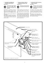
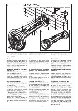
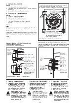
Schieben Sie den Schlauch über den Schlauchnip-
pel des Ventils. Klemmen Sie den Schlauch mit der
Schlauchschelle fest.
Hinweis:
Das Ventil (16) fängt einen eventuell vorkommen-
den Rückstau ab, der sich z.B. bei Verwendung des
Massageschlauches, der Düse für Rückenmassa-
ge oder bei mutwilligen Verschließen der Düse bil-
den kann. Das Ventil verhindert, daß Wasser aus
dem Luftansaugschlauch spritzt.
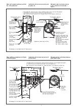
Deshalb das Ventil unbedingt über dem Wasser-
spiegel anbringen.
Das Ventil ist nur dicht, solange sich keine Ablage-
rungen oder Haare darin festsetzen.
Kürzen Sie den Luftansaugschlauch, wenn dieser
länger ist, als Sie ihn benötigen. Je kürzer der Luft-
ansaugschlauch, desto geringer ist sein Widerstand
und umso höher ist der Luftdurchsatz.
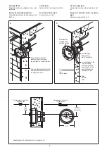
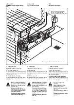
Anschluss Steuerkasten (Bild 5)
Der Steuerkasten (18) sollte entweder in einem tro-
ckenen Umgang oder in einem angrenzenden Raum
untergebracht werden.
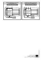
Der Anschluss ist sorgfältig nach DIN VDE 0100 Teil
702 auszuführen. Der Anschluss an das Netz er-
folgt durch eine 5 G 2,5 mm² (3N ~ PE 400V) oder
durch 4 G 2,5 mm² (3 ~ PE 230V) Leitung.
In diese Zuleitung ist sowohl ein Hauptschalter, mit
dem das Gerät allpolig vom Netz getrennt werden
kann, als auch in FI-Schalter vorzusehen. (siehe Hin-
weisblatt: „An den Elektroinstallateur“)
Stecken Sie den 10 m langen PVC-Schlauch, der
vom Düsenmantelgehäuse kommt, auf den Nippel
des PE-Wandlers (19) außerhalb des Steuerkastens
(18).
Push the tube over the straight connector of the val-
ve. Secure the tube with the pipe clamp.
Note:
The purpose of the non return valve (16) is to ab-
sorb back pressure generated by use of the massa-
ge attachments, and to prevent water spraying out
of the air inlet fitting.
The valve will only function properly as long as
no hair/debris or lime deposit accumulates within
it.
Therefore the valve has to be fixed above water
level.Shorten the air inlet tube if it is longer as ne-
cessary.
The shorter the tube, the lesser the resistance and
the higher the volume of air flow.
Mounting the control panel (Fig. 5)
The control panel must not be installed in a cham-
ber. It should be accommodated either in a dry walk-
way behind the pool wall or in an adjacent room.
The connection must be effected carefully in accor-
dance with EN 60335-2-41.
Connection to the power supply is effected by means
of a 5 x 2,5 mm² (3N PE 400V) cable or a 4 x 2,5
mm² (3 PE 230 V) cable.
Both a power switch, with which the unit can be iso-
lated from the power supply on all poles, and an earth
leakage circuit breaker (R.C.C.B.) should be provi-
ded in this cable (see: “Information for the Electrici-
an”). Plug the 10 m length of the PVC tube coming
from the wall niche, onto the free nipple of the “T”
connector (19) outside the control panel (18).
Introduire le raccord de la soupape dans le tuyau.
Fixer le tuyau avec le collier de serrage .
Recommandation
La soupape (16) doit retenir le reflux qui apparaît
lors de l’utilisation du tuyau de massage et de la buse
pour le massage du dos, ou lors de la fermeture in-
tentionnelle de la buse, et doit empêcher que de l’eau
ne jaillisse du tuyau d’aspiration d’air. Une soupape
est hermétiquement étanche tant que des cheveux
ou autre dépôts ne s’y déposent pas.
Monter la soupape impérativement au-dessus du
niveau de l’eau.
Si le tuyau d’aspiration d’air est trop long, il faut le
couper jusqu’à ce qu’il ait la longueur nécessaire.
Plus le tuyau d’aspiration d’air est court, plus la ré-
sistance est faible, vous gagnez ainsi un plus grand
débit d’air.
Raccordement du coffret électrique (fig. 5)
Le coffret électrique ne doit pas être implanté dans
un lieu humide. Il est à placer soit dans un endroit
sec soit dans une pièce avoisinante. Effectuez le
raccordement en respectant les normes en viguer,
notamment les normes DIN VDE 0100 partie 702 et
les normes C 15.100. Le raccordement au réseau
s’effectue par un câble 5 G 2,5 mm² (3 N ~ PE 400
V), par un câble 4 G 2,5 mm² (3 N ~ PE 230 V), ou
par un câble 3 G 2,5 mm² (230 V monophasé).
A cette conduite d’alimentation sera prevu un inter-
rupteur général avec lequel l’appareil peut être cou-
pé du secteur, ainsi qu’un interrupteur différentiel de
30 mA. (voir page „A l’attention de l’électricien).
Fixez le tuyau en PVC long de 10 m, qui provient du
boîtier de la pièce à sceller, sur le raccord libre du
raccordement en T (19) qui se trouve en dehors du
coffret électrique (18).
5
10
15
4
7
6
8
9
11
12
14
1
18
2
13
16
17
3
19
ca. 5-10 cm über dem Wasserspiegel /
/ quelque 5-10 cm au-dessus u niveau d' eau
approx 5-10 cm above water level
5
4