background image

7

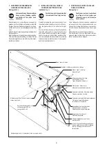
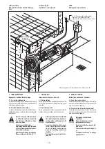
Einbau des Düsenmantelgehäuses in ein Stahl-,
Alu- und Polyesterbecken

Einbau des Düsenmantelgehäuses in ein Becken
mit Überflutungsrinne

Installing the wall niche in deck level pools with
overflow channel

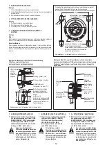
Abmessungen in cm / 

dimensions in cm

 / mesures en cm

Abmessungen in cm / 

dimensions in cm

 / mesures en cm

Saugstutzen /
manchon d' aspiration

suction duct

Betonwandstärke max.

Béton

Concrete /

Oben

haut

label top

Ausschnitt und Bohrungen in der
Beckenwand am besten mit Hilfe
des Klemmrahmens anreissen
bzw. Abbohren

coupure et trous dans la paroi
de la piscine sont façile à faire
avec l' aide du cadre de serrage

use clamping frame for cutting and
drilling realizzare

Düsenmantelgehäuse

pièce à sceller

wall niche

Beckenwand /
paroi piscine

pool wall

Senkschraube M 8 X 35

vis à tête fraisée

sunk screw

Klemmrahmen

cadre de serrage

clamping frame

Dichtung /
joint

gasket

Mittelachse der Düse

niveau de la buse

nozzle center line

Luftansaugschlauch zur Ansaugung der Luft aus dem Beckenumgang 5-10 cm über dem Wasserspiegel

tuyau d' aspiration d' air pour aspiration d' air,  extremité à placer 5-10 cm au-dessus u niveau d' eau

air inlet tube for air suction end part to be installed 5-10 cm above water level

Wasserspiegel /

niveau de l’eau

water level

Wasserspiegel /

niveau de l’eau

water level

Ø 31

20-35

(opt. 25)

Ø 25,6

3,7

24,0

Ø 23,5

Luftschlauch /
Tuyau d' aspirationd’ air

Air inlet

8x45

° =

36

45°

Ø 0,9

Leerrohr für
Pneumatikschlauch

tube pour tuyau
pneumatique

protective sleeve
for pneumatic tube

Kabelschutzschlauch

Gaine de protection
du câble

Protective sleeve

Fertigbecken: Kernbohrung bei 23,5 cm

Installing the wall niche in steel, aluminium and
polyester pools

Ø 31

Ø 25,6

23,7 - 38,7

(optimal 28,7)

3,7

20-35

(opt. 25)

24

~13,5

~8

~42

~35

Saugstutzen

manchon
d' aspiration

suction duct

Düsenmantelgehäuse

/ pièce à sceller

wall niche

Dichtung /

/ joint

gasket

Luftansaugschlauch zur Ansaugung der Luft aus dem Beckenumgang 5-10 cm über dem Wasserspiegel

tuyau d' aspiration d' air pour aspiration d' air,  extremité à placer 5-10 cm au-dessus u niveau d' eau

air inlet tube for air suction end part to be installed 5-10 cm above water level

Wasserspiegel /

niveau de l’eau

water level

Wasserspiegel /

niveau de l’eau

water level

Leerrohr für Pneumatikschlauch

tube pour tuyau pneumatique

protective sleeve for pneumatic tube

Lage der Düse

niveau de la buse

nozzle center line

Bohrungen im Schalbrett
mit Bohrschablone abbohren

faire les percages du coffrage
en utilisant le gabarit

use drilling template for drills
in the shuttering

Schalbrett /
planche de coffrage

shuttering

Montage de la pièce à sceller dans piscines avec
goulotte à débodement

Montage de la pièce à sceller dans piscines
d’ acier, d’ aluminium et de revêtement
Polyester

Содержание DUNA

Страница 1: ...1 DUNA MONTAGE UND BEDIENUNGSANLEITUNG INSTALLATION AND OPERATING INSTRUCTIONS INSTRUCTIONS DE MONTAGE ET MODE D EMPLOI...

Страница 2: ...from the specialist consultant If contrary to expectations technical defects occur in your unit please contact the customer service de partment or your dealer LIST OF CONTENTS PAGE 1 Safety Instructio...

Страница 3: ...h off pump before adjusting angle of nozz le For large area massage reduce the strength to half thrust In order to attach and detach the massage fitting switch off the pump To massage a single part of...

Страница 4: ...wn to the fact that the unit may only be operated in the proper manner If it is operated in an improper manner the user must bear sole responsibility In such cases therefore the manufacturer cannot ac...

Страница 5: ...Sie das D senmantelgeh use b ndig mit der Beckenwand ein Erh lt das Becken f r eine Folienauskleidung einen Putz oder D mmplattenauftrag so m ssen Sie das D senmantelgeh use um die Putz bzw D mmplat...

Страница 6: ...ile 5 cm Fliesenplan Bild 2 Fliesen Sie das D senmantelgeh use bis zu seiner Innenkante Becken mit Folienauskleidung Bild 3 Ordnen Sie Klemmrahmen und die Dichtungen nach Bild 3 an 3 2 Tile plan fig 2...

Страница 7: ...egel niveau de l eau water level 31 20 35 opt 25 25 6 3 7 24 0 2 3 5 Luftschlauch Tuyau d aspirationd air Air inlet 8x45 36 0 45 0 9 Leerrohr f r Pneumatikschlauch tube pour tuyau pneumatique protecti...

Страница 8: ...If the nozzle wouldn t be steered into several directions you have to put out 1 of the plastic disk 9 5 The face plate 2 will be attract with the 2 Screws 1 easily Installing the pump suction and pre...

Страница 9: ...ol wall or in an adjacent room The connection must be effected carefully in accor dance with EN 60335 2 41 Connection to the power supply is effected by means of a 5 x 2 5 mm 3N PE 400V cable or a 4 x...

Страница 10: ...served before setting up and operating 4 2 First time operation Before operating local safety requirements must be met and safety precautions must be observed Before operating the unit for the first t...

Страница 11: ...the amount of air induced 4 6 Massage Before massage you must definite ly reduce the jet pressure Do not utilize full thrust against soft parts of the body For large area massage reduce the strength t...

Страница 12: ...r of water just under the surface is made to flow strongly without excessive effervescence being visible on the water surface 4 8 Winterization If the unit is installed in a pool where there is a dan...

Страница 13: ...ungen in cm dimensions in cm mesures en cm Senkschraube vis T F M 6 x 40 screw Senkschraube vis T F M 6 x 25 screw Spannplatte centre de plaque de fixation clamping plate Befestigungsplatte plaque de...

Страница 14: ...pump DUNA power 400 V 3N AC 50 Hz 2 5 kW 3 5 kW 230 V single phase 50 Hz 3 2 1 7 kW 5 Motor protection The necessary switching and safety elements are accommodated in the control panel and so there is...

Страница 15: ...2 K1 1 2 3 4 5 6 6 5 1 2 PE 1 2 1 2 3 4 1 2 3 4 2 1 1 2 1 3 A1 A2 1 2 A1 A2 3 4 16A 30mA Hauptschalter allpol Trennstelle 4A Die bauseitige Installation ist gem den g ltigen Bestimmungen wie z B DIN V...

Страница 16: ...E TERRE PH3 5 6 1 PH3 POMPE 3 PH3 5 PH3 14 A2 SCHEMA DE BRANCHEMENT A REALISER POMPE POMPES 3 5 kW ou 2 5 kW TRIPHASEES 400 VOLTS Alimentation Difff rentiel 30mA 0bligatoire SCHEMA DE BRANCHEMENT A RE...

Отзывы: