


19
22.
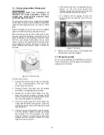
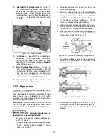
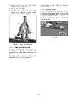
Tailstock Off-Set Adjustment
(D, Figure 17):
Two hex socket cap screws located on the
tailstock base are used to off-set the tailstock
for cutting tapers. Loosening one screw while
tightening the other will off-set the tailstock. Do
not clamp the tailstock lock handle when
adjusting.
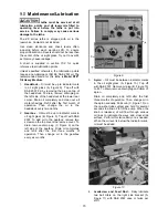
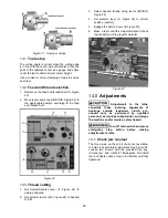
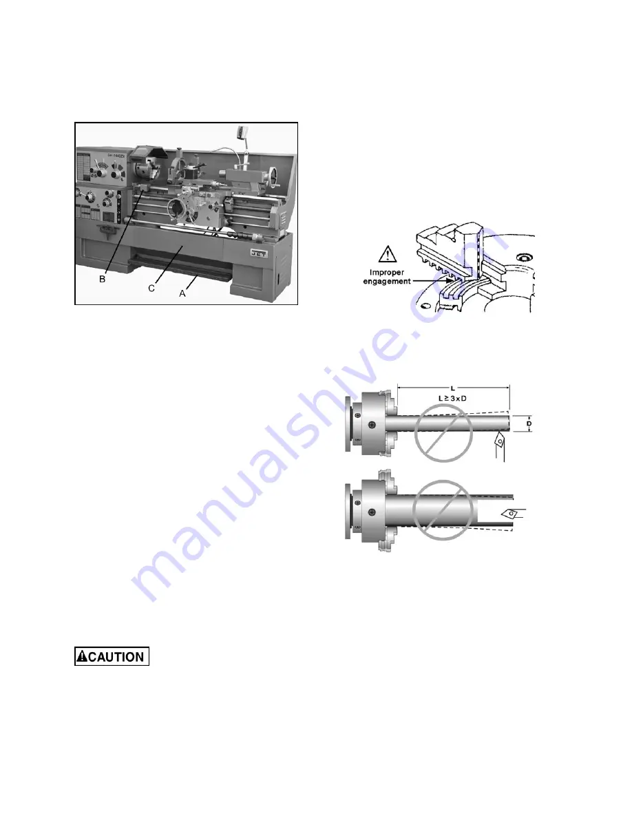
Figure 18 – Other controls
23.
Foot Brake
(A, Figure 18): The connecting rod
mechanism is in the bed stand. The braking
device is in the pulley of the headstock. Press
the pedal to stop all lathe functions. (
Caution:
Lathe still has power.)
24.
Micro Carriage Stop
(B, Figure 18): can be
used during manual feed operation. The dial
can be turned for fine tuning the position of the
stop. The micro carriage stop can be moved
along the bed by loosening the two socket
head cap screws underneath the stop.
25.
Bed Cover
(C, Figure 18): can be easily
removed to clean out the stand.
13.0
Operation
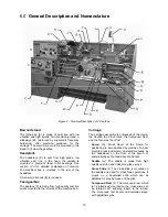
The operator should consult shop manuals such as
“Machinery’s Handbook” for cutting speeds and
feeds appropriate to specific workpieces. Correct
feed depends upon material to be cut, cutting
operation, tool type, chucking rigidity, depth of cut,
and desired surface quality.
IMPORTANT:
Allow a break-in period for the new
lathe so that gears and bearings can adapt; do not
run the lathe above 560 RPM for the first six hours
of operation.
The following points must be
observed when operating the lathe:
•
Never turn any handles or levers when spindle
is at high speed.
•
Change spindle speed only after spindle stops.
•
Change feed rate only when spindle is at low
speed or is stopped.
•
Never exceed maximum speed limitation of the
work holding device.
•
Before starting spindle, check that each handle
or lever is at correct position to ensure normal
engagement of gears. The spindle direction
control lever should be at neutral position.
•
If the brake becomes ineffective, turn off
machine and adjust brake immediately.
•
When operating spindle direction control lever,
always turn it to correct position; never use
“pre-position” for cutting at a reduced speed.
•
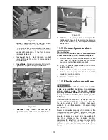
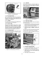
Jaw teeth and scroll must be fully engaged, to
prevent the jaws from breaking and being
thrown from chuck (see Figure 19).
Figure 19 – Insufficient jaw tooth engagement
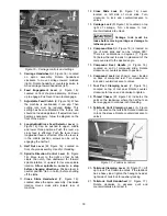
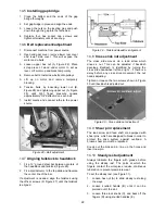
•
Avoid long workpiece extensions, as parts may
bend or fly off (see figure 20). Use rests or the
tailstock for support.
Figure 20 – Improper setups
•
Avoid short clamping contact (Figure 21, A) or
clamping on a minor part diameter (Figure 21,
B). Face-locate the workpiece for added
support.
Содержание GH-1440ZX
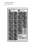
Страница 25: ...25 16 0 Reference tables 16 1 Inch Lead And Feed Table 2 F E E D I N R E V LONGITUDINAL TRANSVERSE ...
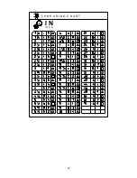
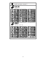
Страница 26: ...26 T H R E A D I N G C H A R T I N I N C H ...
Страница 27: ...27 m m M E T R I C T H R E A D I N G C H A R T M P M O D U L E P I T C H ...
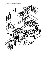
Страница 31: ...3 1 1 Stand Assembly Exploded View ...
Страница 34: ...6 2 1 Brake Assembly Exploded View ...
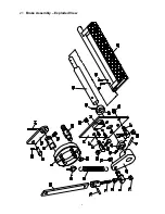
Страница 36: ...8 3 1 Bed Assembly Exploded View ...
Страница 39: ...11 4 1 Headstock Assembly I Exploded View ...
Страница 43: ...15 5 1 Headstock Assembly II Exploded View ...
Страница 46: ...18 6 1 Headstock Assembly III Exploded View ...
Страница 48: ...20 7 1 Headstock Assembly IV Exploded View ...
Страница 50: ...22 8 1 Change Gear Box Assembly I Exploded View ...
Страница 52: ...24 9 1 Change Gear Box Assembly II Exploded View ...
Страница 54: ...26 10 1 Quick Change Gear Box I Exploded View ...
Страница 57: ...29 11 1 Quick Change Gear Box II Exploded View ...
Страница 59: ...31 12 1 Quick Change Gear Box III Exploded View ...
Страница 61: ...33 13 1 Apron Assembly I Exploded View ...
Страница 64: ...36 14 1 Apron Assembly II Exploded View ...
Страница 67: ...39 15 1 Apron Assembly III Exploded View ...
Страница 69: ...41 16 1 Carriage Assembly Exploded View ...
Страница 73: ...45 18 1 Carriage Stop Assembly Exploded View ...
Страница 75: ...47 19 1 Quick Change Tool Post Exploded View ...
Страница 77: ...49 20 1 Tailstock Assembly I Exploded View ...
Страница 79: ...51 21 1 Tailstock Assembly II Exploded View ...
Страница 81: ...53 22 1 Steady Rest Assembly Exploded View ...
Страница 83: ...55 23 1 Follow Rest Assembly Exploded View ...
Страница 85: ...57 24 1 Coolant Work Light Assembly Exploded View ...
Страница 89: ...61 26 2 Electrical Cabinet Breakdown 6 7 8 12 11 10 17 22 21 23 13 9 9a 20 18 3a 1 2 4 19 3 ...
Страница 90: ...62 27 0 Wiring Diagram ...
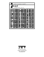
Страница 94: ...66 427 New Sanford Road LaVergne Tennessee 37086 Phone 800 274 6848 www jettools com ...


