

46
18.2
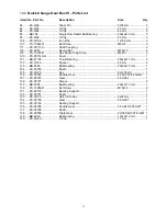
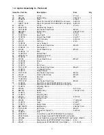
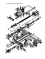
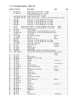
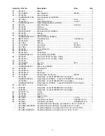
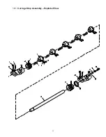
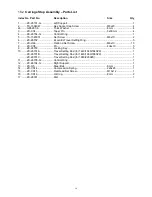
Carriage Stop Assembly – Parts List
Index No Part No
Description
Size
Qty
1 .......... ZX-26101-G .................. Left Support .......................................................... .................................... 1
2 .......... TS-1504041 .................. Hex Socket Cap Screw ........................................ M8x20 ......................... 4
2a ........ GB5287-8 ...................... Thick Washer ....................................................... 8 mm ........................... 4
3 .......... ZX-C34 .......................... Taper Pin .............................................................. 6x30 mm ..................... 4
4 .......... ZX-26704-G .................. Control Ring ......................................................... .................................... 1
5 .......... TS-1523031 .................. Set Screw ............................................................. M6x10 ......................... 2
6 .......... ZX-26702 ...................... Eccentric Travel Setting Ring ............................... .................................... 5
7 .......... ZX-H66 .......................... Flat End Set Screw .............................................. M6x10 ....................... 10
8 .......... ZX-C08 .......................... Pin ........................................................................ 4n6x10 ........................ 5
9 .......... ZX-26703 ...................... Locking Key.......................................................... .................................... 5
10 ........ ZX-26701A .................... Travel Setting Rod (for 1440/1640/1840ZX) ........ .................................... 1
............ ZX-26701B .................... Travel Setting Rod (for 1460/1660/1860ZX) ........ .................................... 1
............ ZX-26701C .................... Travel Setting Rod (for 1880/2280ZX) ................. .................................... 1
11 ......... ZX-26705-G .................. Control Ring ......................................................... .................................... 1
12 ........ ZX-26104-G .................. Right Support ....................................................... .................................... 1
13 ........ ZX-H5 ............................ Steel Ball .............................................................. 8 mm ........................... 1
14 ........ ZX-CS14 ....................... Compression Spring ............................................. 2x8x25 ........................ 1
15 ........ ZX-CS15 ....................... Flat Head Set Screw ............................................ M10x12 ....................... 1
16 ........ ZX-CS16 ....................... Oil Cup ................................................................. 8 mm ........................... 2
17 ........ ZX-26301 ...................... Dial ....................................................................... .................................... 1
Содержание GH-1440ZX
Страница 25: ...25 16 0 Reference tables 16 1 Inch Lead And Feed Table 2 F E E D I N R E V LONGITUDINAL TRANSVERSE ...
Страница 26: ...26 T H R E A D I N G C H A R T I N I N C H ...
Страница 27: ...27 m m M E T R I C T H R E A D I N G C H A R T M P M O D U L E P I T C H ...
Страница 31: ...3 1 1 Stand Assembly Exploded View ...
Страница 34: ...6 2 1 Brake Assembly Exploded View ...
Страница 36: ...8 3 1 Bed Assembly Exploded View ...
Страница 39: ...11 4 1 Headstock Assembly I Exploded View ...
Страница 43: ...15 5 1 Headstock Assembly II Exploded View ...
Страница 46: ...18 6 1 Headstock Assembly III Exploded View ...
Страница 48: ...20 7 1 Headstock Assembly IV Exploded View ...
Страница 50: ...22 8 1 Change Gear Box Assembly I Exploded View ...
Страница 52: ...24 9 1 Change Gear Box Assembly II Exploded View ...
Страница 54: ...26 10 1 Quick Change Gear Box I Exploded View ...
Страница 57: ...29 11 1 Quick Change Gear Box II Exploded View ...
Страница 59: ...31 12 1 Quick Change Gear Box III Exploded View ...
Страница 61: ...33 13 1 Apron Assembly I Exploded View ...
Страница 64: ...36 14 1 Apron Assembly II Exploded View ...
Страница 67: ...39 15 1 Apron Assembly III Exploded View ...
Страница 69: ...41 16 1 Carriage Assembly Exploded View ...
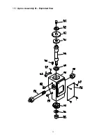
Страница 73: ...45 18 1 Carriage Stop Assembly Exploded View ...
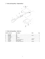
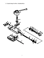
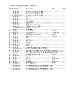
Страница 75: ...47 19 1 Quick Change Tool Post Exploded View ...
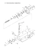
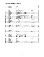
Страница 77: ...49 20 1 Tailstock Assembly I Exploded View ...
Страница 79: ...51 21 1 Tailstock Assembly II Exploded View ...
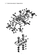
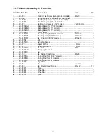
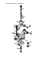
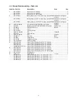
Страница 81: ...53 22 1 Steady Rest Assembly Exploded View ...
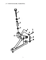
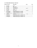
Страница 83: ...55 23 1 Follow Rest Assembly Exploded View ...
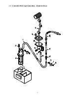
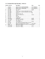
Страница 85: ...57 24 1 Coolant Work Light Assembly Exploded View ...
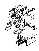
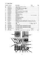
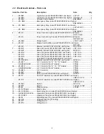
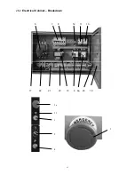
Страница 89: ...61 26 2 Electrical Cabinet Breakdown 6 7 8 12 11 10 17 22 21 23 13 9 9a 20 18 3a 1 2 4 19 3 ...
Страница 90: ...62 27 0 Wiring Diagram ...
Страница 94: ...66 427 New Sanford Road LaVergne Tennessee 37086 Phone 800 274 6848 www jettools com ...


