
18
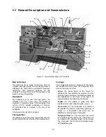
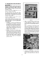
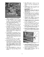
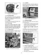
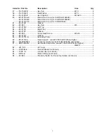
Figure 16 – Carriage controls and settings
5.
Carriage Handwheel
(H, Figure 16): Located
on apron assembly. Rotate handwheel
clockwise to move carriage toward tailstock
(right). Rotate handwheel counterclockwise to
move carriage toward headstock (left).
6.
Feed Engagement Lever
(J, Figure 16):
Located on front of apron assembly. Pull lever
up to engage. Push lever down to disengage.
7.
Adjustable Feed Clutch
(K, Figure 16): When
the machine is overloaded, it can slip. Then
cutting rate must be reduced.
Note:
This
setting has been calibrated at the factory and
should not need adjustment. If adjustment ever
becomes necessary, follow the diagram on the
front of the apron.
8.
Longitudinal/Cross Feed Selector Lever
(L,
Figure 16): Can be pushed to upper, middle
and lower three positions. Push the lever up,
cross feed is effected. Push the lever down,
longitudinal feed is effected. When the lever is
in the middle position, screws can be cut by
engaging the half nut.
9.
Half Nut Lever
(M, Figure 16): Located on
front of apron assembly. Used for threading.
10.
Spindle Direction Control Lever
(N, Figure
16). Move lever to the right so that its tab
clears the notch, then
downward
for forward
spindle rotation, or
upward
for reverse spindle
rotation.
Allow spindle to come to a stop
before changing directions.
Position lever in
neutral position (tab in notch) before shutting
off the lathe.
11.
Cross Slide Handwheel
(P, Figure 16):
Located above the apron assembly. Clockwise
rotation moves cross slide toward rear of
machine.
12.
Cross Slide Lock
(Q, Figure 16): Lever
located on left side of cross slide. Turn
clockwise to lock and counterclockwise to
unlock.
13.
Carriage Lock
(R, Figure 16): Located on top
right of carriage. Turn clockwise to lock,
counterclockwise to unlock.
Carriage lock must be
loose before moving carriage or damage to
lathe may occur.
14.
Compound Rest
(S, Figure 16) is located on
top of cross slide and can be rotated 360°.
There are calibrations in degrees (T, Figure
16) below the rest to assist in placement of the
compound rest to the desired angle.
15.
Compound Rest Handle
(U, Figure 16):
Located on end of compound slide. Rotate
clockwise or counterclockwise to position.
16.
Compound Lock
(not shown): Lever located
on back of compound rest. Turn clockwise to
lock and counterclockwise to unlock.
17.
Tool Post Clamping Lever
(V, Figure 16):
Located on top of tool post. Rotate counter-
clockwise to loosen and clockwise to tighten.
18.
Thread Chaser
(W, Figure 16):
Indicates the
point on the leadscrew where the half nut can
be re-engaged to continue inch threading.
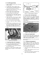
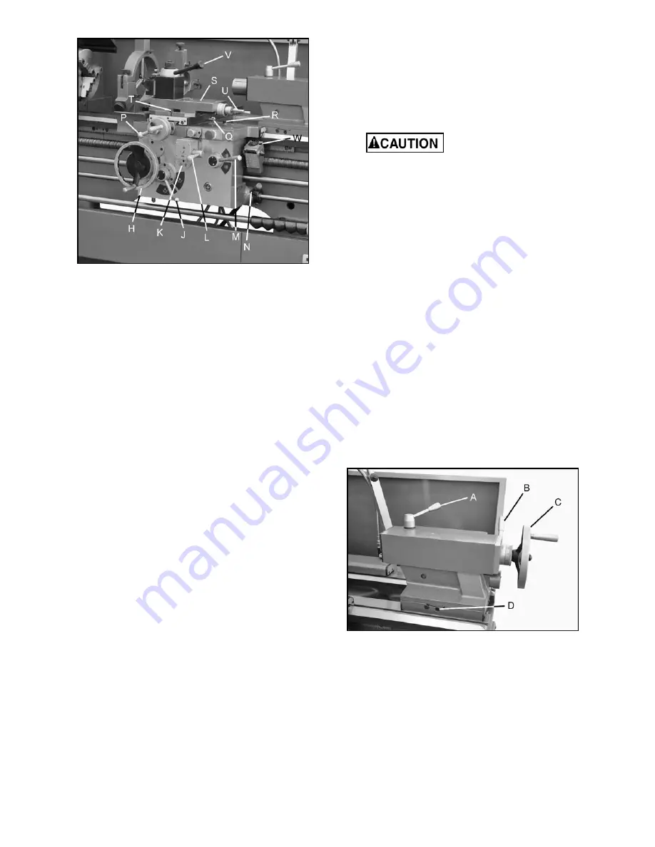
19.
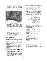
Tailstock Quill Clamping Lever
(A, Figure
17): Located on the tailstock. Rotate clockwise
to lock the sleeve. Rotate counterclockwise to
unlock.
Figure 17 – Tailstock controls
20.
Tailstock Clamping Lever
(B, Figure 17): Lift
up to lock. Push down to unlock. If the tailstock
has a heavy load, tighten the hexagon head at
right side of tailstock for auxiliary locking.
21.
Tailstock Quill Handwheel
(C, Figure 17):
Rotate clockwise to advance quill and
counterclockwise to retract it.
Содержание GH-1440ZX
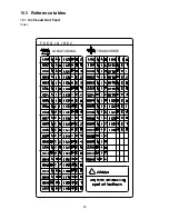
Страница 25: ...25 16 0 Reference tables 16 1 Inch Lead And Feed Table 2 F E E D I N R E V LONGITUDINAL TRANSVERSE ...
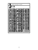
Страница 26: ...26 T H R E A D I N G C H A R T I N I N C H ...
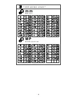
Страница 27: ...27 m m M E T R I C T H R E A D I N G C H A R T M P M O D U L E P I T C H ...
Страница 31: ...3 1 1 Stand Assembly Exploded View ...
Страница 34: ...6 2 1 Brake Assembly Exploded View ...
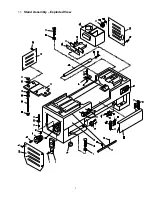
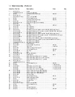
Страница 36: ...8 3 1 Bed Assembly Exploded View ...
Страница 39: ...11 4 1 Headstock Assembly I Exploded View ...
Страница 43: ...15 5 1 Headstock Assembly II Exploded View ...
Страница 46: ...18 6 1 Headstock Assembly III Exploded View ...
Страница 48: ...20 7 1 Headstock Assembly IV Exploded View ...
Страница 50: ...22 8 1 Change Gear Box Assembly I Exploded View ...
Страница 52: ...24 9 1 Change Gear Box Assembly II Exploded View ...
Страница 54: ...26 10 1 Quick Change Gear Box I Exploded View ...
Страница 57: ...29 11 1 Quick Change Gear Box II Exploded View ...
Страница 59: ...31 12 1 Quick Change Gear Box III Exploded View ...
Страница 61: ...33 13 1 Apron Assembly I Exploded View ...
Страница 64: ...36 14 1 Apron Assembly II Exploded View ...
Страница 67: ...39 15 1 Apron Assembly III Exploded View ...
Страница 69: ...41 16 1 Carriage Assembly Exploded View ...
Страница 73: ...45 18 1 Carriage Stop Assembly Exploded View ...
Страница 75: ...47 19 1 Quick Change Tool Post Exploded View ...
Страница 77: ...49 20 1 Tailstock Assembly I Exploded View ...
Страница 79: ...51 21 1 Tailstock Assembly II Exploded View ...
Страница 81: ...53 22 1 Steady Rest Assembly Exploded View ...
Страница 83: ...55 23 1 Follow Rest Assembly Exploded View ...
Страница 85: ...57 24 1 Coolant Work Light Assembly Exploded View ...
Страница 89: ...61 26 2 Electrical Cabinet Breakdown 6 7 8 12 11 10 17 22 21 23 13 9 9a 20 18 3a 1 2 4 19 3 ...
Страница 90: ...62 27 0 Wiring Diagram ...
Страница 94: ...66 427 New Sanford Road LaVergne Tennessee 37086 Phone 800 274 6848 www jettools com ...


