11
EHB-8VS | EHB-8VSM
11.4 SETTING THE VISE FOR ANGLE CUTS
(NON-MITERING VERSION ONLY)
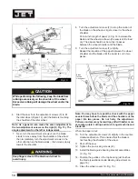
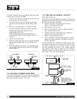
Referring to Figure 9, the vise can be adjusted through a
45-degree arc as follows:
1. Loosen the lock handle (E) that secures the fixed vise
jaw
(D).
2. Rotate the fixed vise jaw (D) to the desired angle,
setting it to the scale on the back edge of the table.
For accurate cuts, use a variable protractor to set the
position of the jaw, aligning one side of the protractor
with the blade.
3. Tighten the lock handle (E).
4. Loosen the hex head bolt (A) on the moveable vise
jaw
(C).
5. Place the workpiece (B) between the vise jaws (C, D).
6. Set the moveable vise jaw (C), pressing it against the
side of the workpiece (B) and fixed vise jaw (D).
7. Tighten the hex head bolt (A) on the moveable vise
jaw to secure the jaw.
11.2 EVALUATING CUTTING EFFICIENCY
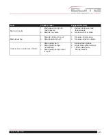
Is the blade cutting efficiently? The best way to determine
this is to observe the chips formed by the cutting blade.
If the chip formation is powdery, then the feed is much too
light, or the blade is dull.
If the chips formed are curled, but colored – blue or straw
colored from heat generated during the cut – then the feed
rate is too high.
If the chips are slightly curled and are not colored by heat
– the blade is sufficiently sharp and is cutting at its most
efficient rate.
11.3 WORK SETUP
Referring to Figure 8:
1. Set the feed rate control knob (C) to zero.
2. With the lifting handle (A) raise the saw head (B).
3. Turn the vise handwheel (D) counter clock-wise
enough to free the moveable vise jaw (E). Then
pull the moveable vise jaw away from the fixed vise
jaw(H).
4. Place the workpiece (F) on the work table (G). For
long workpieces, provide support at the other end. If
necessary, provide additional downward clamping to
hold the workpiece securely on the worktable.
5. Clamp the workpiece (F) in the vise by first pushing
the moveable vise jaw (E) against the workpiece.
Then rotate the vise handwheel (D) clockwise to
secure the workpiece.
Fig. 8
A
B
C
D
E
F
H
G
Fig. 9
A
B
C
D
E


