background image

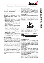
Chlorinator C 2700

BW 2 03 01 / 6

Operating and Maintenance Instructions

Schematic Diagram

1. Chlorine barrel

MB 2 21 01

2. Chlorine barrel valve with flexible coupling

MB 2 22 01

3. Manifold

MB 2 23 01

4. Main shutoff valve

MB 2 24 01

5. Electrical chlorine changeover valve

MB 2 24 01

6. Safety solenoid valve

MB 2 25 01

7. Pressure gauge for changeover device

MB 2 40 01

8. Pressure reducing valve

MB 2 27 01

9. Chlorine gas filter

MB 2 26 01

10. Chlorinator

MB 2 03 01

11. Electrical chlorine gas control valve

MB 2 07 10

12. Shutoff ball cock
13. Ejector non-return valve

MB 2 32 01

14. Ejector

MB 2 31 02

15. Non-return valve
16. Shutoff valve with solution injection

MB 2 34 01

Legend

17. Safety blowoff line
18. Filter
19. Shutoff valve

MB 2 29 04

20. Booster pump

MB 2 29 01

21. Control cabinet
22. Solenoid valve for sprinkler valve

MB 2 36 10

23. Manual shutoff valve for sprinkler system

accessible from outside

MB 2 36 10

24. Sprinkler jet

MB 2 36 10

25. Sensors of the gas warning device

MB 2 36 05

Note:
Not all of the system components shown are absolutely
necessary. The scope of installation should be planned carefully
by a specialist.

Chlorine deposits may cause servere problems. To avoid
these, use a pressure reducing valve (8).

14

13

12

10

25

7

8

9

5

11

24

3

4

4

6

17

15

21

22

23

19

19

20

18

16

2

1

Lutz-Jesco GmbH

Improved changes are always reserved without notice.

Содержание C 2700

Страница 1: ...ach room is to be provided with small ventilation openings in the floor and ceiling These openings must directly lead outside and their cross sections should not exceed 40 cm2 In the case of unfavoura...

Страница 2: ...r first by means of a manifold 3 A main shutoff valve 4 is mounted on the output A steel or copper pipe connects this valve to the inlet valve of the chlorinator For automatic cutoff of the chlorine g...

Страница 3: ...en with nuts d by turns so that the receiving blocks are parallel to each other The prepared measuring set is fixed to the base plate Now tighten the spacer bolts c gently by turns Fasten the flanges...

Страница 4: ...alves If the barrel connecting valve 2 leaks the gland stud must be retightened by about a quarter turn For this purpose the handwheel of the valve must be removed This can be done under gas pressure...

Страница 5: ...by an authorized specialist firm at least once a year Preferably this should happen at the beginning of a high rate period prior to a downtime or a restart General The vacuum systems described need l...

Страница 6: ...ector MB 2 31 02 15 Non return valve 16 Shutoff valve with solution injection MB 2 34 01 Legend 17 Safety blowoff line 18 Filter 19 Shutoff valve MB 2 29 04 20 Booster pump MB 2 29 01 21 Control cabin...

Страница 7: ...losses due to friction in pipes wrong gluing or fittings Check joints Float stuck in flow meter glass Clean flow meter as described under Maintenance Components under vacuum prime Check the joints of...

Отзывы: