Testing Procedures
!
WARNING
To avoid risk of electrical shock, personal injury or death; disconnect power to cooktop before servicing, unless
testing requires power.
©2004 Maytag Services
16023537
13
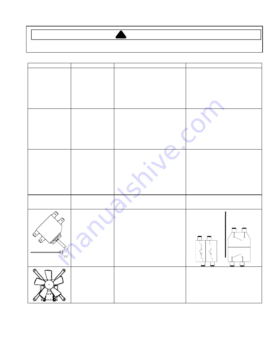
Component Testing
Illustration Component
Test
Procedure
Results
Power supply
Disconnect power from cooktop and
verify circuit breakers/fuses are not
tripped. Check fuse rating. Check
terminals at terminal block for
tightness. Verify cooktop service wires
are properly connected, and are in
good condition. Check for proper
voltage with a voltmeter .........................
Refer to schematic diagram for correct
voltage measurements
Internal wiring
Disconnect power from cooktop, place
one ohmmeter lead at the terminal
block, the other lead at the line terminal
of the malfunctioning part. Use the
appropriate wiring diagram to repeat this
procedure from the output of the control
to the component, until each section is
checked. A visual check of the wiring
will often determine the fault location .....
Continuity
1200 W
−
6”
1800 W
−
7”
2000 W
−
8”
3000 W
−
9/6”
(Dual element)
3000 W
−
12/9/6”
(Triple element)
Ribbon radiant
elements
Remove one wire lead from element
and measure resistance of element .......
Dual element
−
1400 + 1600 = 3000 W....
Triple element
−
1050/2200/2700 W ........
Continuity (approximately), if not replace.
6”
−
1200W: 44 to 49
Ω
7”
−
1800W: 29 to 33
Ω
8”
−
2000W: 26 to 30
Ω
3000W: 1400 W Inner 53 to 59
Ω
1600 W Outer 38 to 42
Ω
Triple:
1050 W: 52 to 57
Ω
2200 W 24 to 28
Ω
2700 W 19 to 24
Ω
100 W
Warming element
Remove one wire lead from element
and measure resistance of element .......
Continuity, if not replace
6”
−
100W:
35 to 39
Ω
Approx
Ribbon surface
thermal limiter/hot
light switch
Turn surface element on and test for
voltage. See wiring diagram and
schematic ..............................................
1a
−
2a 240
VAC
1b
−
2b 120
VAC
Disconnect leads and measure
resistance on the following:
1a
−
2a room
temperature
−
continuity
1b
−
2b room
temperature
−
infinite
240 VAC
Electrovac
1b
1a
2a
2b
Hot light
Heater
circuit
circuit
Therm-O-Disc (TOD)
1b
2b
2a
1a
Hot light
Heater
circuit
circuit
Cooling fan
Remove wire leads from terminals and
measure resistance of the motor............
Verify voltage to cooling fan terminals....
Should indicate resistance. If infinite
ohms, replace cooling fan
120 VAC See Wiring Diagram/Schematic
for terminal identification
RPM: 2100 ± 400
Содержание JEC0530ADB
Страница 17: ...2004 Maytag Services 16023537 A 1 Appendix A...
Страница 21: ...2004 Maytag Services 16023537 B 1 Appendix B...


