


Subject to change without notice!
Installation and Operating Instructions ECOVARIO® 616, 616 D
49
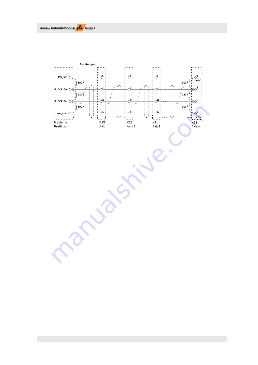
All units are connected in a bus structure (line). In one segment up to 32 participants (master or slaves) can
be connected. Each segment has an active bus terminating module at the beginning and at the end (cf. Fig.
6.41).
To obtain faultless operation it has to be made sure that both bus terminating modules are continuously
supplied. Th e bus terminating module is commonly realized in the bus connectors to be switched in. If there
are more than 32 participants or for enlarging the network repeaters have to be used to connect the bus
segments to each other.
Use only cable with a mesh shield. If the unit is mounted it is an advantage if the cable is stripped without
interruption and laid on the shield or PE conductor. Th is measure increases the reliability in ambients with
strong interferences.
For newly installed PROFIBUS DP-V0 cablings we recommend standardized cable type A with the follow-
ing characteristics:
Wave resistance:
135 – 165 Ω
Capacitance per unit length:
< 30 pF/m
Loop resistance:
110 Ω/km
Core diametre:
0,64 mm
Core cross section:
> 0,34 mm²
Th e maximum cable length depends on the transmission rate. E. g. with a transmission rate of 187.5 kBit/s
the maximum cable length is 1 200 m, at 12 MBit/s the cable should not be longer than 100 m.
At transmission rates ≥1.5 MBit/s spur lines must be avoided. Common connectors provide the possibility
to connect incoming and outgoing cables directly in the connector. Th us spur lines are avoided and the bus
connector can be plugged in and off the bus without interrupting the data transmission.
Use only bus connectors suitable for PROFIBUS DP-V0 and the respective baud rate. Th e connectors at both
ends should provide a termination to be switched in. Additionally in each connector should be a longitudi-
nal inductance with 100 nH for each outgoing data conductor. Th ese connectors are available from Siemens
for example.
Th e shield of the PROFIBUS DP-V0 cable may not be used for potential compensation. Machines that are
grounded at various spots must have a separate PE conductor the impedance of which is at least 10 times
smaller than the one of the cable shields.
Fig. 6.41: PROFIBUS connection of several ECOVARIO® axes


