background image


14

3)


Coupling 


1.


See chapter 5, Technical characteristics, page 8. 


2.


Hitching the machine to the tractor must only be carried out using the tractor’s rear 
coupling points provided for this purpose. 


3.


Check the compatibility of the machine with the tractor (minimum engine power, type 
of coupling, tractor PTO characteristics, etc.). Keep clear of the area between the tractor 
and the machine until you have stopped the tractor’s engine and removed the starter key.  


4.


Keep clear of the area between the tractor and the machine during any lifting manoeuvre 
of the tractor. 


5.


When manoeuvring, select the lowest possible tractor gear ratio. When coupling, attach 
the equipment’s electric control unit in the tractor cab, ensuring that it cannot move 
during operations. 


6.


Once the equipment has been coupled up, the hitch must be locked. Check the coupling 
is correctly locked and in good condition before any movement. 


7.


Check that the equipment’s coupling does not create either an overload or poor weight 
distribution on the tractor that might compromise stability: 
  - Do not exceed the maximum allowed loading for the tractor and equipment 
attachment points. 
  - Where necessary, fit ballast weights to the mounts provided for this purpose in 
accordance with the tractor manufacturer’s recommendations.  
Couple the equipment to a tractor whose linkage is equipped with lateral and vertical 
locking devices. 


8.


To drive on roads, respect the coupling height specified in the instruction manual.  


4)


PTO (power take-off) / Drive shaft 


1.


Read and learn the manufacturer’s instructions for the drive shaft, attached to the 
transmission. 


2.


Check that the PTO guards are in place and in a good condition. Replace them 
immediately if damaged. 


3.


Adjust the length between the tractor and the machine, retaining maximum engagement. 


4.


The minimum engagement length is 

250mm

. See white instruction stickers placed on 

the front of the unit, n° 892 640 (page 12).  
Before each operation, check that the drive shaft is in good condition and that it is fitted 
and locked correctly. 


5.


Only use the drive shaft provided with the equipment or recommended by the 
manufacturer. 


6.


Check before each use that the speed and direction of rotation of the tractor PTO are 
compatible with the planned usage of the equipment. 


Содержание EVR 8-6

Страница 1: ...P1 35590 L HERMITAGE France Tel 00 33 0 2 99 64 04 04 Fax 00 33 0 2 99 64 19 56 Spare parts shop tel 00 33 0 2 99 64 04 02 Spare parts shop fax 00 33 0 2 99 64 09 36 E mail jeantil jeantil com Web sit...

Страница 2: ...tifies important advice that must be followed for your safety When you see this symbol be aware that there is a potential risk of injury read carefully the advice that follows it and inform other user...

Страница 3: ...EVR 18 14 EVR 18 14T EVR 21 15 SERIAL N COMPLIES WITH 1 Labour regulations 2 The revised European equipment directive N 98 37 EC 3 Revised EMC directive electromagnetic compatibility N 89 336 EC 4 Sp...

Страница 4: ...onmental conditions p 7 e Manufacturer s and user s responsibilities p 8 5 Technical characteristics p 8 1 Dimensions p 8 2 Stowing diagram p 10 6 General safety rules p 11 1 General p 11 2 Warning Pi...

Страница 5: ...p 27 10 Start up and operation p 27 11 Uses p 27 1 Spreading quantity per hectare p 27 2 Loading p 28 3 Spreading p 29 4 When the spreading is finished p 30 12 Additional equipment information p 30 1...

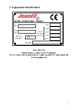
Страница 6: ...uction P T A C R ceptionn Masses maximales admissibles Anneau Essieu 1 Essieu 2 kg kg kg kg 20 kg Essieu 3 35590 L HERMITAGE FRANCE Ref 892 770 Manufacturer s plate to EC standards Never remove the ma...

Страница 7: ...ied all the safety instructions Once working it will be too late to do this c Defining the operating stations 1 The only operating station for the equipment is the tractor s driving station 2 Never le...

Страница 8: ...recommendations 3 Do not carry out any modifications yourself and do not allow others to modify your equipment and its accessories mechanical electrical hydraulic or pneumatic characteristics without...

Страница 9: ...1 20 m 1 20 m 1 20 m 1 40 m 1 40 m 1 40 m 1 40 m 1 40 m 1 40 m 1 40 m E Overall length 6 40 m 6 40 m 6 85 m 7 35 m 7 85 m 7 35 m 7 35 m 7 85 m 7 85 m 8 45 m 8 45 m 9 45 m F Overall width 2 55 m 2 55 m...

Страница 10: ...10 2 Stowing diagram...

Страница 11: ...form and means of access to the work station 8 Before carrying out any work on the equipment ensure that it cannot be started up accidentally 9 All controls ropes cables rods hoses etc must be positio...

Страница 12: ...3 If repairs are carried out check that the replacement parts carry the same stickers as those that have been removed Ref 892 640 SAFETY AND OPERATING STICKER CLEARLY placed IN FULL VIEW on the front...

Страница 13: ...92 230 Plac l avant de l pandeur Ref 892 687 Placed on the rear right and left sides of spreader Ref 892 230 Placed at the front of the spreader Ref 892 652 Placed next to parts which need greasing Se...

Страница 14: ...ht compromise stability Do not exceed the maximum allowed loading for the tractor and equipment attachment points Where necessary fit ballast weights to the mounts provided for this purpose in accorda...

Страница 15: ...fficient operation 3 Check the cleanliness of the oil 4 Respect maintenance periods Before any servicing or repair 5 Check the stability of the machine and its components 6 Lower the equipment to the...

Страница 16: ...the tractor engine and remove the starter key 3 Before working on the hydraulic system check that the installation is not under pressure 4 Eliminate pressure before disconnecting hydraulic lines 5 Be...

Страница 17: ...containers designed for the purpose Avoid using containers used for food or drink bottles 3 Used tyres It is against the law to store tyres or to dump them dispose of them in the natural environment...

Страница 18: ...e shaft is located between the spreader s longitudinal main shaft and the vertical beater drive It is equipped with a declutchable cam limiter on the spreaders 10 6 to 21 15 or with a shear bolt on th...

Страница 19: ...ing problems activate the tractor distributor and immediately use the equipment s hydraulic functions b As soon as the equipment s hydraulic functions have been used return the tractor s distributor t...

Страница 20: ...points are arranged as follows 1 Drawbar pin 2 2 Front shaft of moving floor left and right side 1 Left 1 Right 3 Upper bearings of spreading device 1 Left 1 Right 4 Rear shaft of moving floor left a...

Страница 21: ...floor Rollboden 2 l SAE 90 ROCHLING 7 EVR 12 8 to 15 12 814 136 Fond mouvant Moving floor Rollboden 2 4 l SAE 90 ROCHLING 8 EVR 14 11 to 16 12 814 130 Fond mouvant Moving floor Rollboden 2 l SAE 90 RO...

Страница 22: ...5x32 Alliance 347 1 80 m 0 62 m 5490 1 7 12 5 842142 23 1x26 Alliance 347 1 60 m 0 59 m 4880 2 0 14 6 842256 650 75R32 Alliance A360 1 80 m 0 63 m 6990 3 2 Radial 7 842130 or 842253 600 60x30 5 Trell...

Страница 23: ...alibrate or decalibrate screw or unscrew the valve s adjusting screw and control with pressure gauge 7 SAFETY VALVE OF HYDRAULIC DOOR 1 Valve N 825 246 fitted on the lower port piston side of one of t...

Страница 24: ...EPAN 5 WALTERSCHEID 1 It protects the spreading device against overload foreign matters and an excessive speed of the moving floor 2 Located on the secondary transmission K64 22R 3 The jaw with freewh...

Страница 25: ...determine the length of the spring pack dimension A and after removing the elastic pin to adjust the limiter according to the table bellow Limiter type Exterior diameter Spring type Number of springs...

Страница 26: ...or the tractor s PTO 540 or 1000revs min and do not slow down in spite of the constant noise produced by the two beating cams The limiter can remain disengaged for a certain time without risks for the...

Страница 27: ...t goes round once 4 In case of frost check that the guillotine door is working option 11 Uses 1 SPREADING QUANTITY PER HECTARE I Determine the weight to be loaded 1 Manure density D P1 weight of conta...

Страница 28: ...ssary to spread a new set quantity Q2 of manure if one knows the quantity of manure Q1 in tonnes to spread per hectare and the speed of the tractor V1 in km h 1 V2 V1 x Q1 Q2 2 Example Q1 40 tonnes pe...

Страница 29: ...ntrol the moving floor can have a regular or variable speed Use A With hydraulic control from the tractor pump pressurize the power circuit engaging the tractor distributor B With independent hydrauli...

Страница 30: ...ional equipment information 1 INDEPENDENT HYDRAULIC POWER UNIT Price ref 2236 1 PUMP MODEL 540 revs min EVR 8 6 10 6 12 8 13 10 15 12 N 821019 2 PUMP MODEL 1000 revs min EVR 14 11 14 12 16 12 18 14 21...

Страница 31: ...er is automatically activated 3 REAR DOOR FOR THICK SLURRY Price ref 2860 2862 SAFETY 1 Carefully check that the door is not in contact with an electric line as there is a potential risk of electrocut...

Страница 32: ...NANCE 1 Change oil at least once a year 2 Oil quality Mineral oil HFO 32 UNIL OPAL 3 Oil quantity 4 litres 5 DUAL ACTING HYDRAULIC PUMP Price ref 2147 N 891 008 It is equipped with a double pilot valv...

Страница 33: ...nteed by a cam limiter at the entry of the lower gearbox which protects the entire device and by the declutchable cam limiter on the side transmission which protects the horizontal beaters 3 3 F Fu un...

Страница 34: ...ning 13 a Cleaning method Cover all parts that need protection from water penetration or from cleaning products Periodically wash the equipment with a water hose If a high pressure water hose is used...

Страница 35: ...istributor components 45L min 904 061 1 A Single acting manual pump 904 024 1 A Dual acting hydraulic stand 904 027 1 A Level indicator 904 031 1 A Two way valve 904 036 1 A Safety plug valve ALFAGOMM...

Страница 36: ...10 15 12 904 156 1 A Set of 3 angle transmission gearboxes Berma EVR 10 6 12 8 13 10 15 12 904 039 1 A Set of 3 angle transmission gearboxes GB EVR EPAN 5 EVR 14 11 14 12 16 12 18 14 21 15 904 157 1...

Страница 37: ...or speed EVR 8 6 904 132 1 A Moving floor speed EVR 10 6 904 085 1 A Moving floor speed EVR 12 8 904 133 1 A Moving floor speed EVR 13 10 904 134 1 A Moving floor speed EVR 15 12 904 135 1 A Moving fl...

Страница 38: ...ctor filter 2 Lack of hydraulic power 4 Tractor pump failure flow and pressure 1 Back pressure on hydraulic return see hydraulic connection 2 Reduce flow to 45 l min 3 Damaged hydraulic motor seal 1 T...

Страница 39: ...39...

Страница 40: ...40...

Отзывы: