


7 - 2
Checking/Adjusting the Track Tension
1. Prepare the Machine
Position the machine on level ground. Run it backwards
and forwards several times. Stop after running it
forwards.
Carry out steps 1 to 3 of
Cleaning the Tracks
. Block up
the undercarriage frame. Finish track rotation by running
the track forwards. Stop the engine and remove the
starter key.
!
!
WARNING
NEVER position yourself or any part of your body under a
raised machine which is not properly supported. If the
machine moves unexpectedly you could become
trapped and suffer serious injury or be killed.
INT-3-3-7
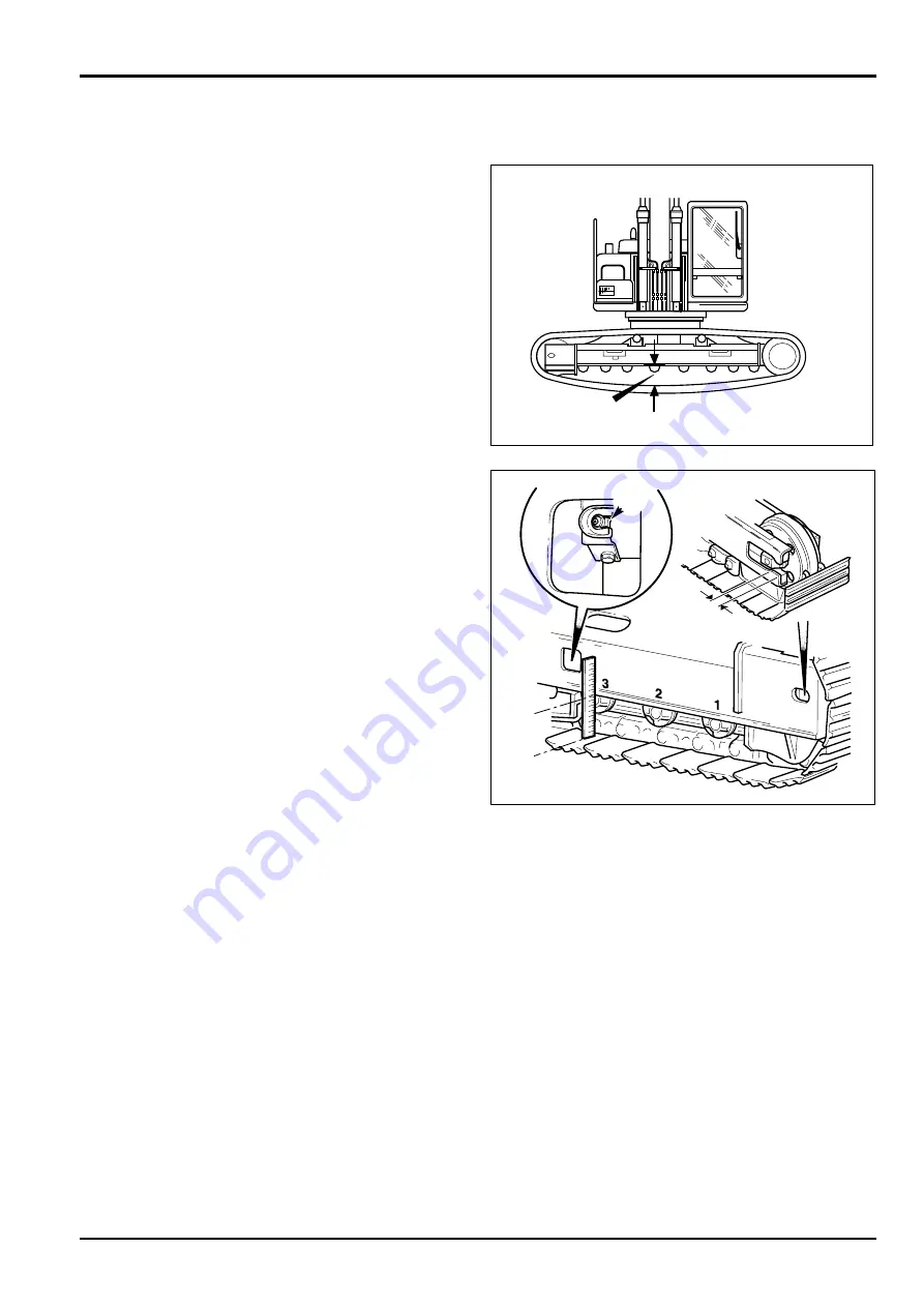
2. Check the Tension
Measure gap
A
in line with the fourth roller from the front
and between the lower surface of the track frame and
the upper surface of the shoe. The dimension should be
275-295 mm for hard ground conditions. For operation
on soft sand or sticky mud it should be 320-340 mm.
3. Adjust the Track Tension
Adjustment is made by either injecting or releasing
grease from the check valve
B
. Inject grease to reduce
the gap (increase the tension) or open to release grease
and increase the gap.
!
!
WARNING
When opening the check valve always stand to one side
and loosen a little at a time until grease starts to come
out. If you over-loosen too much grease could spurt out
or the valve cover fly out and cause serious injury.
8-3-4-5
!
!
WARNING
Under no circumstances must the check valve be
dismantled or any attempt made to remove the grease
nipple from the check valve.
8-3-4-9
If gap
C
exists between the idler wheel shaft and the
track frame, you may use pressure to apply the grease. If
there is no gap
C
after the application of grease, then the
necessary repairs must be carried out.
Note:
Excessive tension can cause the track rail to wear the
drive rollers and sprocket, insufficient tension can cause
wear to the drive sprocket and track rail.
4. Lower the Track
Remove the blocks from beneath the undercarriage and
lower the track to the ground using the boom and dipper
controls.
5. Repeat for the Opposite Track
Slew the boom round to the other side and repeat steps
1 to 4 above.
Section 3
Routine Maintenance
9803/6400
Section 3
7 - 2
Issue 3*
Tracks and Running Gear
(continued)
JS03770
A
*
*
A343970
B
B
C
C
A
A
Содержание JS 200 Series
Страница 57: ...9 1 Section 3 Routine Maintenance 9803 6400 Section 3 9 1 Issue 2 Component Location Diagram...
Страница 67: ...2 1 Section B Body Framework 9803 6400 Section B 2 1 Issue 2 Undercarriage Dimensions JS200 JS220...
Страница 68: ...2 2 Section B Body Framework 9803 6400 Section B 2 2 Issue 2 Undercarriage Dimensions JS200LC JS220LC...
Страница 69: ...2 3 Section B Body Framework 9803 6400 Section B 2 3 Issue 2 Undercarriage Dimensions JS240 JS260...
Страница 70: ...2 4 Section B Body Framework 9803 6400 Section B 2 4 Issue 2 Undercarriage Dimensions JS240LC JS260LC...
Страница 113: ......
Страница 137: ...5 3 Section C Electrics 9803 6400 Section C 5 3 Issue 2 Pump Control FLOW CHART...
Страница 140: ...5 6 Section C Electrics 9803 6400 Section C 5 6 Issue 1 Pump Control Cushioned Boom Starting continued Flow Chart...
Страница 143: ...5 9 Section C Electrics 9803 6400 Section C 5 9 Issue 1 Pump Control Pressure Increasing System continued Flow Chart...
Страница 150: ...5 16 Section C Electrics 9803 6400 Section C 5 16 Issue 1 Pump Control Power Supply Cut Delay Flow Chart...
Страница 154: ...5 20 Section C Electrics 9803 6400 Section C 5 20 Issue 1 Pump Control Swing brake Swing lock continued Flow Chart...
Страница 155: ...5 21 Section C Electrics 9803 6400 Section C 5 21 Issue 1 Pump Control Lever Lock Circuit Diagram Time Chart...
Страница 157: ...5 22 Section C Electrics 9803 6400 Section C 5 22 Issue 1 Pump Control Lever Lock continued Flow Chart...
Страница 201: ...10 7 Section C Electrics 9803 6400 Section C 10 7 Issue 1 CAPs II Diagnostic system K C...
Страница 215: ...Section E Section E Hydraulics 9803 6400 Issue 2 3 2 3 2 Schematics...
Страница 217: ...Section E Section E 9803 6400 Issue 2 3 3 3 3 Hydraulics Schematics...
Страница 218: ...3 5 Section E Hydraulics 9803 6400 Section E 3 5 Issue 1 Schematics Shuttle Block JS200 JS240...
Страница 232: ...10 1 Section E Hydraulics 9803 6400 Section E 10 1 Issue 1 Hydraulic Pump JS200 JS240...
Страница 233: ...10 2 Section E Hydraulics 9803 6400 Section E 10 2 Issue 1 Hydraulic Pump JS200 JS240...
Страница 234: ...10 3 Section E Hydraulics 9803 6400 Section E 10 3 Issue 1 Hydraulic Pump JS200 JS240...
Страница 263: ...30 2 Section E Hydraulics 9803 6400 Section E 30 2 Issue 1 Control Valve JS200 JS240...
Страница 264: ...30 3 Section E Hydraulics 9803 6400 Section E 30 3 Issue 1 Control Valve JS200 JS240...
Страница 265: ...30 4 Section E Hydraulics 9803 6400 Section E 30 4 Issue 1 Control Valve JS200 JS240...
Страница 266: ...30 5 Section E Hydraulics 9803 6400 Section E 30 5 Issue 1 Control Valve JS200 JS240...
Страница 267: ...30 6 Section E Hydraulics 9803 6400 Section E 30 6 Issue 1 Control Valve JS200 JS240...
Страница 268: ...30 7 Section E Hydraulics 9803 6400 Section E 30 7 Issue 1 Control Valve JS200 JS240...
Страница 276: ...31 8 Section E Hydraulics 9803 6400 Section E 31 8 Issue 1 Control Valve JS200 JS240 Operation continued...
Страница 277: ...31 9 Section E Hydraulics 9803 6400 Section E 31 9 Issue 1 Control Valve JS200 JS240 Operation continued...
Страница 278: ...31 10 Section E Hydraulics 9803 6400 Section E 31 10 Issue 1 Control Valve JS200 JS240 Operation continued Travel Fig 4...
Страница 279: ...31 11 Section E Hydraulics 9803 6400 Section E 31 11 Issue 1 Control Valve JS200 JS240 Operation continued...
Страница 280: ...31 12 Section E Hydraulics 9803 6400 Section E 31 12 Issue 1 Control Valve JS200 JS240 Operation continued...
Страница 281: ...31 13 Section E Hydraulics 9803 6400 Section E 31 13 Issue 1 Control Valve JS200 JS240 Operation continued...
Страница 282: ...31 14 Section E Hydraulics 9803 6400 Section E 31 14 Issue 1 Control Valve JS200 JS240 Operation continued...
Страница 283: ...31 15 Section E Hydraulics 9803 6400 Section E 31 15 Issue 1 Control Valve JS200 JS240 Operation continued...
Страница 286: ...31 18 Section E Hydraulics 9803 6400 Section E 31 18 Issue 1 Control Valve JS200 JS240 Operation continued...
Страница 314: ...50 2 Section E Hydraulics 9803 6400 Section E 50 2 Issue 1 Solenoid Valve 8 spool JS200 JS240 Schmatics Technical Data...
Страница 327: ...51 12 Section E Hydraulics 9803 6400 Section E 51 12 Issue 1 Solenoid Valve 8 spool...
Страница 328: ...55 1 Schematic Section E Hydraulics 9803 6400 Section E 55 1 Issue 1 Shuttle Valve...
Страница 330: ...55 3 Schematic Section E Hydraulics 9803 6400 Section E 55 3 Issue 1 Cushion Valves...
Страница 363: ...75 10 Section E Hydraulics 9803 6400 Section E 75 10 Issue 1 Hydraulic Rams Ram Piston Head Nut JS00980...
Страница 442: ...2 2 Schematics specifications Section F Transmission 9803 6400 Section F 2 2 Issue 1 Motor Gearbox...
Страница 452: ...3 10 Section F Transmission 9803 6400 Section F 3 10 Issue 1 Motor Gearbox Fig 8 1 1st Speed Fixed Mode...
Страница 481: ...7 15 Section F Transmission 9803 6400 Section F 7 15 Issue 2 Motor...
Страница 482: ...7 16 Section F Transmission 9803 6400 Section F 7 16 Issue 1 Motor...
Страница 530: ...Contents Page No Routine Maintenance See Section 3 Technical Data 1 1 i Engine 9803 6400 i Issue 1 Section K Section K...


