


4 - 4
Slew Motor Pressure Relief
1. Prepare the machine
Put the operators lever into neutral, lower the gate lock
lever. Start the engine and place the machine on level
ground, lower and open the dipper and set the bucket on
the ground. Stop the engine.
2.
Release the hydraulic oil tank pressure.
(See
Releasing Tank Pressure
)
.
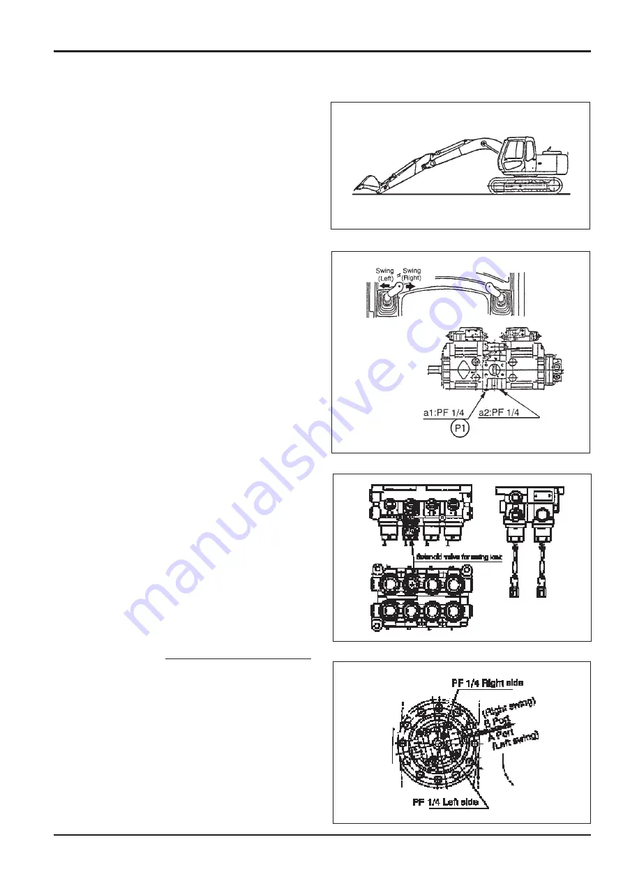
3.
Connect a 0-500 bar (0-7000 lb/in
2
) pressure gauge and
adaptor to the port marked P1 on the pump.
4. Initiate slew lock procedures.
a.
Remove the water-proof connector on the slew lock
solenoid valve, which is on the hydraulic pump side.
b.
Press the slew lock switch which is on the left hand
console inside the cab, and confirm that the slew
(swing) lock symbol appears on the monitor.
c.
Start the engine, and operate the engine at around
1000 r.p.m, then operate the slew lever slowly. Listen
to confirm that the relief sound is heard and that the
machine does not slew.
d.
Run the engine at maximum no-load speed and in the
S
mode.
e.
Operate the slew lever.
5.
Confirm the pressure of 299.8 ± 14.4 bar (4408 ± 213
lb/in
2
) at the gauge.
Notes:
1.
If the water-proof slew lock solenoid valve is not
removed, slew lock status can be obtained with the
slew lock switch
ON
, but slew relief is not carried out.
2.
Wire colour code to the solenoid is Dark Green.
3.
Pressure measurement is also possible on the slew
motor, upper section.
6.
If the pressure is within the limits, stop engine release
tank pressure and remove the gauge and adaptor; If the
readings are outside the limits, continue as below.
7. Pressure Adjustment
a.
Confirm the present pressure reading.
b.
The difference between the set pressure and the
present pressure determines the number of shims
F
required for adjustment.
The No of shims = Set pressure-Present Pressure
4.83 bar (71.1 lb/in
2
)
8.
Remove the relief valve assembly from the slew motor.
Note:
If both relief valves are removed at the same time,
mark them left and right to facilitate reassembly in the
correct position.
Section E
Hydraulics
9803/6400
Section E
4 - 4
Issue 2*
Pressure Testing
*
Содержание JS 200 Series
Страница 57: ...9 1 Section 3 Routine Maintenance 9803 6400 Section 3 9 1 Issue 2 Component Location Diagram...
Страница 67: ...2 1 Section B Body Framework 9803 6400 Section B 2 1 Issue 2 Undercarriage Dimensions JS200 JS220...
Страница 68: ...2 2 Section B Body Framework 9803 6400 Section B 2 2 Issue 2 Undercarriage Dimensions JS200LC JS220LC...
Страница 69: ...2 3 Section B Body Framework 9803 6400 Section B 2 3 Issue 2 Undercarriage Dimensions JS240 JS260...
Страница 70: ...2 4 Section B Body Framework 9803 6400 Section B 2 4 Issue 2 Undercarriage Dimensions JS240LC JS260LC...
Страница 113: ......
Страница 137: ...5 3 Section C Electrics 9803 6400 Section C 5 3 Issue 2 Pump Control FLOW CHART...
Страница 140: ...5 6 Section C Electrics 9803 6400 Section C 5 6 Issue 1 Pump Control Cushioned Boom Starting continued Flow Chart...
Страница 143: ...5 9 Section C Electrics 9803 6400 Section C 5 9 Issue 1 Pump Control Pressure Increasing System continued Flow Chart...
Страница 150: ...5 16 Section C Electrics 9803 6400 Section C 5 16 Issue 1 Pump Control Power Supply Cut Delay Flow Chart...
Страница 154: ...5 20 Section C Electrics 9803 6400 Section C 5 20 Issue 1 Pump Control Swing brake Swing lock continued Flow Chart...
Страница 155: ...5 21 Section C Electrics 9803 6400 Section C 5 21 Issue 1 Pump Control Lever Lock Circuit Diagram Time Chart...
Страница 157: ...5 22 Section C Electrics 9803 6400 Section C 5 22 Issue 1 Pump Control Lever Lock continued Flow Chart...
Страница 201: ...10 7 Section C Electrics 9803 6400 Section C 10 7 Issue 1 CAPs II Diagnostic system K C...
Страница 215: ...Section E Section E Hydraulics 9803 6400 Issue 2 3 2 3 2 Schematics...
Страница 217: ...Section E Section E 9803 6400 Issue 2 3 3 3 3 Hydraulics Schematics...
Страница 218: ...3 5 Section E Hydraulics 9803 6400 Section E 3 5 Issue 1 Schematics Shuttle Block JS200 JS240...
Страница 232: ...10 1 Section E Hydraulics 9803 6400 Section E 10 1 Issue 1 Hydraulic Pump JS200 JS240...
Страница 233: ...10 2 Section E Hydraulics 9803 6400 Section E 10 2 Issue 1 Hydraulic Pump JS200 JS240...
Страница 234: ...10 3 Section E Hydraulics 9803 6400 Section E 10 3 Issue 1 Hydraulic Pump JS200 JS240...
Страница 263: ...30 2 Section E Hydraulics 9803 6400 Section E 30 2 Issue 1 Control Valve JS200 JS240...
Страница 264: ...30 3 Section E Hydraulics 9803 6400 Section E 30 3 Issue 1 Control Valve JS200 JS240...
Страница 265: ...30 4 Section E Hydraulics 9803 6400 Section E 30 4 Issue 1 Control Valve JS200 JS240...
Страница 266: ...30 5 Section E Hydraulics 9803 6400 Section E 30 5 Issue 1 Control Valve JS200 JS240...
Страница 267: ...30 6 Section E Hydraulics 9803 6400 Section E 30 6 Issue 1 Control Valve JS200 JS240...
Страница 268: ...30 7 Section E Hydraulics 9803 6400 Section E 30 7 Issue 1 Control Valve JS200 JS240...
Страница 276: ...31 8 Section E Hydraulics 9803 6400 Section E 31 8 Issue 1 Control Valve JS200 JS240 Operation continued...
Страница 277: ...31 9 Section E Hydraulics 9803 6400 Section E 31 9 Issue 1 Control Valve JS200 JS240 Operation continued...
Страница 278: ...31 10 Section E Hydraulics 9803 6400 Section E 31 10 Issue 1 Control Valve JS200 JS240 Operation continued Travel Fig 4...
Страница 279: ...31 11 Section E Hydraulics 9803 6400 Section E 31 11 Issue 1 Control Valve JS200 JS240 Operation continued...
Страница 280: ...31 12 Section E Hydraulics 9803 6400 Section E 31 12 Issue 1 Control Valve JS200 JS240 Operation continued...
Страница 281: ...31 13 Section E Hydraulics 9803 6400 Section E 31 13 Issue 1 Control Valve JS200 JS240 Operation continued...
Страница 282: ...31 14 Section E Hydraulics 9803 6400 Section E 31 14 Issue 1 Control Valve JS200 JS240 Operation continued...
Страница 283: ...31 15 Section E Hydraulics 9803 6400 Section E 31 15 Issue 1 Control Valve JS200 JS240 Operation continued...
Страница 286: ...31 18 Section E Hydraulics 9803 6400 Section E 31 18 Issue 1 Control Valve JS200 JS240 Operation continued...
Страница 314: ...50 2 Section E Hydraulics 9803 6400 Section E 50 2 Issue 1 Solenoid Valve 8 spool JS200 JS240 Schmatics Technical Data...
Страница 327: ...51 12 Section E Hydraulics 9803 6400 Section E 51 12 Issue 1 Solenoid Valve 8 spool...
Страница 328: ...55 1 Schematic Section E Hydraulics 9803 6400 Section E 55 1 Issue 1 Shuttle Valve...
Страница 330: ...55 3 Schematic Section E Hydraulics 9803 6400 Section E 55 3 Issue 1 Cushion Valves...
Страница 363: ...75 10 Section E Hydraulics 9803 6400 Section E 75 10 Issue 1 Hydraulic Rams Ram Piston Head Nut JS00980...
Страница 442: ...2 2 Schematics specifications Section F Transmission 9803 6400 Section F 2 2 Issue 1 Motor Gearbox...
Страница 452: ...3 10 Section F Transmission 9803 6400 Section F 3 10 Issue 1 Motor Gearbox Fig 8 1 1st Speed Fixed Mode...
Страница 481: ...7 15 Section F Transmission 9803 6400 Section F 7 15 Issue 2 Motor...
Страница 482: ...7 16 Section F Transmission 9803 6400 Section F 7 16 Issue 1 Motor...
Страница 530: ...Contents Page No Routine Maintenance See Section 3 Technical Data 1 1 i Engine 9803 6400 i Issue 1 Section K Section K...


