9 - 17
Section C
Electrics
9803/6400
Section C
9 - 17
Issue 1
Fault Finding
Fault Diagnosis
(continued)
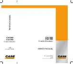
Engine Trouble, Problem No 11
(continued)
Troubleshoot
Cause
Remedy
Engine system
Inspect
Abnormality
engine
system.
Breakage of LR
wiring between stop
Repair
motor connector
LR wiring.
and CND or between
CND and fuse
Replace
Stop motor defect
stop motor.
Shut down relay
Replace
defect
shut down
relay 1.
Shut down relay 2
Replace
Defect or breakage
shut down
of L wiring between
relay 2 or
shut down 1 and 2
repair L
wiring.
Is fuel cut lever on stop side
YES
YES
YES
NO
NO
NO
NO
Remove the stop motor connector
and connect female side (cab side)
to service connector (6 pin).
Measure voltage between LR and
ground, connecting LR to + and
ground to -.
Is it within the range of 20~30V.
Key switch
ON
YES
Measure voltage between shut
down relay 1 connector L and
ground, connecting L to + and
ground to -.
Is the following true?
Emergency stop button ON: 0V
Emergency stop button OFF:
20~30V
Remove the stop motor
connector and attach service
connector to female side.
Confirm continuity between L and
LW. Is the following true?
Key switch ON: Continuity
Key switch OFF: °°
To judge if relay is defective
or not, interchanging the
relay with one in the
centralized relay is another
method.
Содержание JS 200 Series
Страница 57: ...9 1 Section 3 Routine Maintenance 9803 6400 Section 3 9 1 Issue 2 Component Location Diagram...
Страница 67: ...2 1 Section B Body Framework 9803 6400 Section B 2 1 Issue 2 Undercarriage Dimensions JS200 JS220...
Страница 68: ...2 2 Section B Body Framework 9803 6400 Section B 2 2 Issue 2 Undercarriage Dimensions JS200LC JS220LC...
Страница 69: ...2 3 Section B Body Framework 9803 6400 Section B 2 3 Issue 2 Undercarriage Dimensions JS240 JS260...
Страница 70: ...2 4 Section B Body Framework 9803 6400 Section B 2 4 Issue 2 Undercarriage Dimensions JS240LC JS260LC...
Страница 113: ......
Страница 137: ...5 3 Section C Electrics 9803 6400 Section C 5 3 Issue 2 Pump Control FLOW CHART...
Страница 140: ...5 6 Section C Electrics 9803 6400 Section C 5 6 Issue 1 Pump Control Cushioned Boom Starting continued Flow Chart...
Страница 143: ...5 9 Section C Electrics 9803 6400 Section C 5 9 Issue 1 Pump Control Pressure Increasing System continued Flow Chart...
Страница 150: ...5 16 Section C Electrics 9803 6400 Section C 5 16 Issue 1 Pump Control Power Supply Cut Delay Flow Chart...
Страница 154: ...5 20 Section C Electrics 9803 6400 Section C 5 20 Issue 1 Pump Control Swing brake Swing lock continued Flow Chart...
Страница 155: ...5 21 Section C Electrics 9803 6400 Section C 5 21 Issue 1 Pump Control Lever Lock Circuit Diagram Time Chart...
Страница 157: ...5 22 Section C Electrics 9803 6400 Section C 5 22 Issue 1 Pump Control Lever Lock continued Flow Chart...
Страница 201: ...10 7 Section C Electrics 9803 6400 Section C 10 7 Issue 1 CAPs II Diagnostic system K C...
Страница 215: ...Section E Section E Hydraulics 9803 6400 Issue 2 3 2 3 2 Schematics...
Страница 217: ...Section E Section E 9803 6400 Issue 2 3 3 3 3 Hydraulics Schematics...
Страница 218: ...3 5 Section E Hydraulics 9803 6400 Section E 3 5 Issue 1 Schematics Shuttle Block JS200 JS240...
Страница 232: ...10 1 Section E Hydraulics 9803 6400 Section E 10 1 Issue 1 Hydraulic Pump JS200 JS240...
Страница 233: ...10 2 Section E Hydraulics 9803 6400 Section E 10 2 Issue 1 Hydraulic Pump JS200 JS240...
Страница 234: ...10 3 Section E Hydraulics 9803 6400 Section E 10 3 Issue 1 Hydraulic Pump JS200 JS240...
Страница 263: ...30 2 Section E Hydraulics 9803 6400 Section E 30 2 Issue 1 Control Valve JS200 JS240...
Страница 264: ...30 3 Section E Hydraulics 9803 6400 Section E 30 3 Issue 1 Control Valve JS200 JS240...
Страница 265: ...30 4 Section E Hydraulics 9803 6400 Section E 30 4 Issue 1 Control Valve JS200 JS240...
Страница 266: ...30 5 Section E Hydraulics 9803 6400 Section E 30 5 Issue 1 Control Valve JS200 JS240...
Страница 267: ...30 6 Section E Hydraulics 9803 6400 Section E 30 6 Issue 1 Control Valve JS200 JS240...
Страница 268: ...30 7 Section E Hydraulics 9803 6400 Section E 30 7 Issue 1 Control Valve JS200 JS240...
Страница 276: ...31 8 Section E Hydraulics 9803 6400 Section E 31 8 Issue 1 Control Valve JS200 JS240 Operation continued...
Страница 277: ...31 9 Section E Hydraulics 9803 6400 Section E 31 9 Issue 1 Control Valve JS200 JS240 Operation continued...
Страница 278: ...31 10 Section E Hydraulics 9803 6400 Section E 31 10 Issue 1 Control Valve JS200 JS240 Operation continued Travel Fig 4...
Страница 279: ...31 11 Section E Hydraulics 9803 6400 Section E 31 11 Issue 1 Control Valve JS200 JS240 Operation continued...
Страница 280: ...31 12 Section E Hydraulics 9803 6400 Section E 31 12 Issue 1 Control Valve JS200 JS240 Operation continued...
Страница 281: ...31 13 Section E Hydraulics 9803 6400 Section E 31 13 Issue 1 Control Valve JS200 JS240 Operation continued...
Страница 282: ...31 14 Section E Hydraulics 9803 6400 Section E 31 14 Issue 1 Control Valve JS200 JS240 Operation continued...
Страница 283: ...31 15 Section E Hydraulics 9803 6400 Section E 31 15 Issue 1 Control Valve JS200 JS240 Operation continued...
Страница 286: ...31 18 Section E Hydraulics 9803 6400 Section E 31 18 Issue 1 Control Valve JS200 JS240 Operation continued...
Страница 314: ...50 2 Section E Hydraulics 9803 6400 Section E 50 2 Issue 1 Solenoid Valve 8 spool JS200 JS240 Schmatics Technical Data...
Страница 327: ...51 12 Section E Hydraulics 9803 6400 Section E 51 12 Issue 1 Solenoid Valve 8 spool...
Страница 328: ...55 1 Schematic Section E Hydraulics 9803 6400 Section E 55 1 Issue 1 Shuttle Valve...
Страница 330: ...55 3 Schematic Section E Hydraulics 9803 6400 Section E 55 3 Issue 1 Cushion Valves...
Страница 363: ...75 10 Section E Hydraulics 9803 6400 Section E 75 10 Issue 1 Hydraulic Rams Ram Piston Head Nut JS00980...
Страница 442: ...2 2 Schematics specifications Section F Transmission 9803 6400 Section F 2 2 Issue 1 Motor Gearbox...
Страница 452: ...3 10 Section F Transmission 9803 6400 Section F 3 10 Issue 1 Motor Gearbox Fig 8 1 1st Speed Fixed Mode...
Страница 481: ...7 15 Section F Transmission 9803 6400 Section F 7 15 Issue 2 Motor...
Страница 482: ...7 16 Section F Transmission 9803 6400 Section F 7 16 Issue 1 Motor...
Страница 530: ...Contents Page No Routine Maintenance See Section 3 Technical Data 1 1 i Engine 9803 6400 i Issue 1 Section K Section K...