12
Varyscan
®
4 1200 HMI
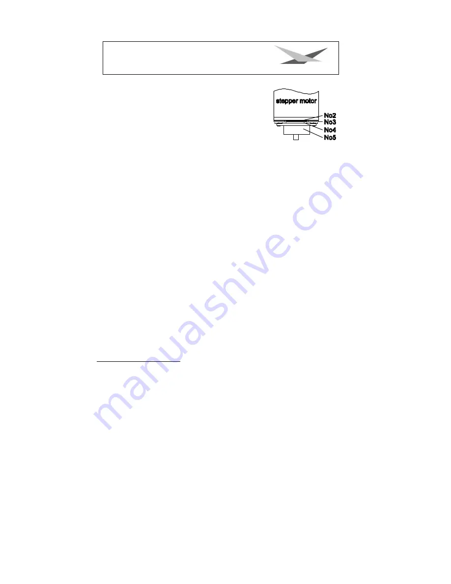
Part no. 1.
motor
Part no. 2.
Tellerfedern
Part no. 3.
Stahllaserteil
Part no. 4.
Kunststoffscheibe
Part no. 5.
zu montierendes Teil
Part no. 5 has to be pushed on the axis of the stepper motor until
the parts no. 2 can not be compressed anymore. After remove the
part no. 5 about 0,5 mm and turn the fastening screws. The
"motor-brake" is now optimum adjusted .
Regular Maintenance Performances
Warning
: Before open the appliance pull out mains plug!
Open the casing by turning out the screws at the top of the Varyscan
®
.
To be able to take out the slide-in modules of your Varyscan
®
, you have to screw off two screws
of silver at the side-piece, up to the mark of the slide-in modules. Now you are able to take out
the slide-in modules (sketch page 4).
Attention
:
Do not forget to lock in the slide-in modules after having completed
your maintenance performances, by screwing in the screws of silver
carefully!
1. Cleaning of all optical parts
You should clean the optical parts of your Varyscan
®
periodically to restore maximum brightness
of the scan. After having opened the casing as explained above, take out the effect wheel slide-in
(see sketch page 4) and put it on an underlay in front of you. Take a fuzz-free rag and a detergent
for windows and clean the effect filters on the effect wheel.
Subsequently clean both lenses (sketch page 4). In order to clean the lens easily, loosen the
screw which fixes the lens and remove the lens. Now it is easy to clean from the outside and the
inside. Take out the colour wheel slide-in in order to clean the dichroitic filters. Put in the lens,
the effect wheel slide-in and the colour wheel slide-in. Do not forget to tighten the screw which
fixes the lens.
2. Cleaning of ventilation
You should check regularly the function of the ventilators. Above all take care that ventilation
inlets and the interior of the Varyscan* are free from fuzzes and other dust. Open both lids of your
Varyscan
®
, by screwing off the screws from the lids. Now clean your Varyscan* carefully with a
vacuum cleaner. Now screw down the lid. Take care that you use the sheet metal screws for
closing the smaller lid.