

Page 4
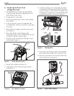
3. Remove the white cap covering the comm hole
(see Figure 6).
4. Thread the controller cable through the hole. A
grommet may be necessary depending on the size of
the cable being used.
5. Attach a cable tie to the controller cable as shown
(see Figure 6).
6
. The Jandy
AquaLink
®
RS or PDA and power pack
use a four (4) wire connection to communicate
and can be wired up to 500 ft (152.4 m) apart.
Any outdoor rated four conductor cable, minimum
22 AWG (0.33 mm
2
), can be used. Locate the
appropriate screw terminals on the circuit board and
wire the power pack
to the AquaLink
RS or PDA
red 4-pin terminal bar (see Figure 7).
NOTE
The screw terminals on the AquaLink RS or
PDA are removable to aid in installation.
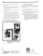
D. Testing the Connection
Once the power pack has been wired to the AquaLink
RS Control System or PDA, follow these steps to test
the connection:
1. Apply power to the power pack and the AquaLink
RS Control System or PDA.
2. Wait about 20 seconds. If the connection was
successful, a
Ŧ
symbol will appear in the top right
corner of the power pack display.
NOTE
If the power pack does not connect to the
controller, turn the power off to both devices
and repeat steps 1 and 2. If the power pack
still does not connect to the controller, re-check
the wiring connections (see Figure 7) and
the controller setting on the power pack (see
Section 4.B).
Figure 7.
Communication Wiring between Power
Pack and AquaLink RS Control System
or PDA Network
Jandy
Power Center
Power Pack
OPTIONAL
4 3 2 1
RED
BLK
YEL
GRN
Red, 4-Pin
Terminal Bar
RED
GRN
YEL
BLK
B
A
0V
POS
RED
BLK
© 2010 Zodiac Pool Systems, Inc. All rights reserved. 0110
ZODIAC POOL SYSTEMS, INC.
2620 Commerce Way • Vista, CA • 92081
Tel: 800-822-7933 • Fax: 877-327-1403
H0342800 Rev -
ETL Listed
Conforms To
UL STD 1081
Certified to
CAN/CSA C22.2 NO. 218.1


