

Page 2
A. Replacing the Power Pack
(Plugged Version)
8. Reattach the terminal cap on the cell.
9. Plug the flow switch cable into the power pack
(see Figure 3).
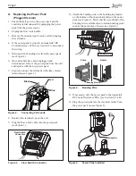
Figure 3.
Flow Switch Connector
Figure 4.
Bonding Wire
Flow Swtich
Connector
1. Ensure that all power to the power pack and the
controller is disconnected by uplugging the power
pack from the power source.
2. Unplug the flow switch cable.
3. Remove the terminal cap from the cell and unplug
the cell leads.
4. If the power pack is wired to an AquaLink
®
RS
Control System or PDA, see Section 4 to disconnect
the wiring.
5. Disconnect the bonding wire from the power pack
(see Figure 4).
6. Once all cables have been unplugged and
disconnected, remove the power pack from the wall
and replace with the new power pack.
7. Securely connect the cell leads to the like colored
terminals (see Figure 2).
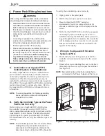
Figure 5.
Power Pack Installed
Bonding Wire
10. Attach the bonding wire to the bonding lug located
on the bottom of the chassis backplate on the power
pack (see Figure 4). Verify that the second end of the
bonding wire is attached to a common bonding point
such as the pool pump or heater (see Figure 4).
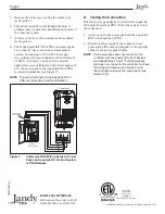
Figure 2.
Connecting Cell Leads
Red
Red
Blue
Black
Bonding Wire
Bonding Lug
Pump
Heater
Bonding Wire
11. If necessary, wire the power pack to the AquaLink
RS Control System or PDA (see Section 4.C- 4.D).
12. Plug the power pack into the electrical outlet. Turn
the power pack on (see Figure 5).