background image

JD-N2


INDEX / WARRANTY 

 JD-N2 

Section D-29

TABLE OF CONTENTS 

Section A 

WARNINGS AND PRECAUTIONS ....................................................................... 2


Wiring Diagram ..................................................................................................... 4


Electrician’s notes ................................................................................................. 5


Section B 

Unpacking ............................................................................................................. 7


Mounting Hardware Required ............................................................................... 7


General installation guidelines .............................................................................. 8


JD-N2 Control ............................................................................................................... 8


Electrical Cables ........................................................................................................... 8


Electrical Power ............................................................................................................ 9


Mounting ....................................................................................................................... 9


Connection Procedure ........................................................................................ 10


Detailed Wiring Diagrams ........................................................................................... 10


Typical Sensor Wiring for Probes ..........................................................................................10


Typical Power Backup Wiring ................................................................................................11


Typical Alarm Connection Wiring ...........................................................................................12


Powering Up Procedure ...................................................................................... 13


Verify all Connections ................................................................................................. 13


Hermetically Close the JD-N2 ..................................................................................... 13


Put the power on ......................................................................................................... 13


Secure the front panel with a lock ............................................................................... 13


Downloading the Configuration ........................................................................... 14


Uploading the Configuration ............................................................................... 15


JD-N2


Compatible Probes ................................................................................... 16


Specifications ...................................................................................................... 17


Troubleshooting .................................................................................................. 18


TABLE OF FIGURES 

FIGURE NO. 1  Mounting Position and Devices ................................................... 9


FIGURE NO. 2  Typical Temperature Probe Wiring ............................................ 10


FIGURE NO. 3  Typical Power Backup Wiring .................................................... 11


FIGURE NO. 4  Typical Alarm Connection Wiring .............................................. 12


FIGURE NO. 5  Typical Siren Connection Wiring ............................................... 12


Содержание JD-N2

Страница 1: ...UAL JD N2 Installation User s Guide ATTENTION ELECTRICIAN SEE WIRING DETAILS ON PAGES A 3 TO A 5 AND ADDITIONAL INFORMATION IN SECTION B USER S GUIDE INSTALLATION GUIDE INDEX WARRANTY WIRING DIAGRAM 7 3 3 ...

Страница 2: ...ipment may damage this equipment For added security against line voltage surges it is recommended that surge and noise suppression devices be installed at the electrical distribution panel Use of shielded cable for probes is recommended for protection against lightning These devices are available from most electrical supply distributors RECOMMENDATIONS The manufacturer recommends that all installa...

Страница 3: ...JD N2 WIRING DIAGRAM JD N2 Section A 3 WIRING DIAGRAM JD N2 SECTION A ...

Страница 4: ... SEE NOTES ON NEXT PAGE REL 1 REL 2 1314 A 5 4 ON OFF BOARD L2 N L1 GNA PRB 1 ALARM 5 N0 C NC 5 L1 L2 N TEMP PROBE 6 7 THE JD N2 MUST BE ON AN INDEPENDENT CIRCUIT WARNING SET LINE VOLTAGE TO CORRECT VALUE BEFORE ATTEMPTING TO OPERATE THE COMPUTER LINE VOLTAGE SELECTOR 230V JD N2 1319 A CLOSE OPEN COM WINCH L2 N L1 ...

Страница 5: ...AC 24VDC ALWAYS CROSS HIGH AND LOW VOLTAGE WIRES AT A 90 DEGREE ANGLE RELAYS 12A 240VAC RESISTIVE MOTOR 1HP 240VAC 1 2HP 120VAC AT EACH OUTPUT 1 WIRE ONLY PER GREEN TERMINAL USE WIRE CONNECTOR IF YOU WANT TO CONNECT MORE THAN 1 WIRE NO BIGGER THAN AWG 12 NO SMALLER THAN AWG 28 CHECK INSTALLATION GUIDE FOR ALARM WIRING USE SHIELD FOR SHIELDING PURPOSE ONLY CONNECT THE SHIELD TO GROUND PLATE NEVER L...

Страница 6: ...JD N2 INSTALLATION JD N2 Section B 6 INSTALLATION JD N2 SECTION B ...

Страница 7: ...pect contents for damage Should the contents appear to be damaged contact your local distributor to return the material The package should contain the following standard items 1 JD N2 control 4 Brackets 4 screws 1 2004 10K inside temperature probe 30 feet cable 1 Installation User s Guide Mounting Hardware Required This is the list of the mounting hardware needed which is not included with the pro...

Страница 8: ...p or the rear of the control Do not install the JD N2 control near high voltage equipment power supply or transformer Electrical Cables All electrical cables must be installed according to local wiring codes All cable shields must be connected to the JD N2 power ground only The shield is needed to protect the JD N2 against any electromagnetic interference generated by lightning or nearby operating...

Страница 9: ...ounted in a location that will allow the cover to be completely opened right up against the wall Fasten the four brackets to the four mounting holes on the back of the enclosure using the four screws provided with the brackets Then mount the enclosure on the wall by inserting screws through the brackets adjustment slots into the wall Make sure to position the enclosure so that all wires extend out...

Страница 10: ...ves the most accurate temperature reading to achieve optimum ventilation The sensor should also be connected to the JD N2 with a shielded two wire cable It should be located in an area protected from operating machinery animal bites personnel or anything that could damage the sensor See also General installation guidelines FIGURE NO 2 Typical Temperature Probe Wiring SHIELD TEMP PROBE ...

Страница 11: ...source 1 is disabled The backup relay should be selected to ensure it is able to support the required power load FIGURE NO 3 Typical Power Backup Wiring 8 PIN RELAY DPDT OMRON model MK2EP UA AC120 3 4 5 6 2 1 8 7 NO 2 NO 1 NC 1 NC 2 COM 2 COM 1 L2 N GND L1 3 4 5 6 2 1 8 7 L2 L1 GND source 1 DISTRIBUTION PANEL L2 L1 N LINE 115 230 VAC source 2 DISTRIBUTION PANEL LINE 115 230 VAC ...

Страница 12: ...used to signal a power failure or other malfunctions It may be connected to an alarm system or directly to a siren and or auto dialer Make the normally closed NC or normally open NO connections as indicated in figures 4 and 5 FIGURE NO 4 Typical Alarm Connection Wiring ALARM SYSTEM AUTO DIALER ALARM N0 C NC L1 L2 N JD N2 1319 A FIGURE NO 5 Typical Siren Connection Wiring Normally closed manual OFF...

Страница 13: ... mounted on the wall and all modules and sensors connected to the terminal block perform the following step Verify all Connections Seal all cable entry holes Hermetically Close the JD N2 Close the front panel and the lower access cover Put the power on Secure the front panel with a lock ...

Страница 14: ... chip MMX and place it in the bottom part of the enclosure or in another safe location Once the MMX Chip is removed the JD N2 starts up and executes the configuration 2 Downloading while the JD N2 is powered up A Remove the faceplate screws and lift up the cover B Place the MMX chip into the socket of the main board At this moment the MMX Detected parameter will appear C Adjust the MMX Detected pa...

Страница 15: ...d parameter will appear D Adjust the MMX Detected parameter to upLD and press the and buttons for two seconds The display on the front panel should indicate upLD for approximately 15 seconds If upLD is not displayed try one more time If upLD is still not displayed remove and replace the configuration chip MMX E When the uploading procedure is complete remove the configuration chip MMX and place it...

Страница 16: ...mpatible Probes This is the list of all compatible probes that can be connected with JD N2 control with a short description of their function Temperature probe 2004 10K black cap Temperature probe with a temperature range of 58 to 140 F 50 to 60 C ...

Страница 17: ...ength 500 feet 150 m Recommended wires 2 conductors stranded shielded AWG 22 ALARM RELAY Maximum current 1 A at 30VDC OUTPUT RELAYS Maximum Current 1HP 240VAC 1 2HP 120VAC 12A 240VAC Caution Notice These relays are rated by UL and CSA at 1HP 240VAC 1 2HP 120VAC However for outputs requiring frequent activation it is recommended not to use more than 1 2HP 240VAC 1 4HP 120VAC per relay Important Not...

Страница 18: ...ormal range replace the probe Temperature probe reads HI Temperature is above 140 F 60 C Probe is short circuited or defective Check all connections If the problem persists and the temperature is within normal range replace the probe Displays are blank JD N2 is not powered Flat cable between the main and top boards of the JD N2 is disconnected Make sure the control is powered Make sure the fuse is...

Страница 19: ...JD N2 USER S GUIDE JD N2 Section C 19 USER S GUIDE JD N2 SECTION C ...

Страница 20: ...JD N2 USER S GUIDE JD N2 Section C 20 Control Description 7 3 3 5 1 2 3 4 6 ...

Страница 21: ...rammable settings After a setting is selected its value appears on the LED display If the value is flashing it can be changed with the value setting buttons and 5 Value Setting Buttons and The value buttons appear as 2 squares with a and sign on them They are used to increase or decrease the value on the LED window Press the button once and release it to increase or decrease the value by one incre...

Страница 22: ...Outputs Qty Inside Temperature 1 Curtain 1 Alarm 1 Equipment Item Description Qty JD N2 Controller 2 On Off Outputs 1 2004 10k Temperature Sensor 58 F to 140 F 50 C to 60 C 1 Configuration Versions Version Minimum processor Version Date Modification V0 2 02 18 2010 New ...

Страница 23: ...E JD N2 Section C 23 Ventilation System Overview This configuration uses 1 natural ventilation curtain which operates according an indoor temperature sensor An alarm check will be made to check if the probe is defective ...

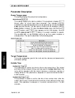
Страница 24: ... Alarm Set Point 2 Sensor has reached High Alarm Set Point 3 Sensor is defective or unplugged 101 The controller has reset 10 times and each reset was less than 15 minutes apart from the last one 102 If this error code appears contact your distributor 103 If this error code appears contact your distributor Target Temperature This is the temperature goal for the room and the reference temperature f...

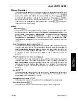
Страница 25: ...Temperature alarm set point Set 2 This parameter sets the temperature below which a low temperature alarm condition will occur When the temperature sensor s reading decreases to Low Temperature alarm set point or below the alarm relay and LED will be activated and the Curtain Idle Time will be overridden This parameter is adjusted in 0 1 increments from OFF 0 1 F to 99 8 F 17 7 C to 37 7 C High Te...

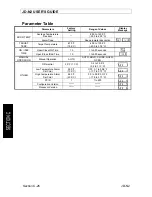
Страница 26: ...0 0 to 37 8 C ON IDLE TIME Open Close ON Time 10 1 to 900 seconds ON Open Close IDLE Time 10 1 to 900 seconds Idle MANUAL OPERATION Manual Operation AUTO AUTO HOLD CLOSE HOLD OPEN OTHER Differential 2 0 F 1 1 C 0 4 to 19 9 F 0 2 to 11 1 C Set 1 Low Temperature Alarm Set Point 50 0 F 10 0 C OFF 0 1 to 99 8 F 17 7 to 37 7 C Set 2 High Temperature Alarm Set Point 86 0 F 30 0 C 0 0 to 99 8 F OFF 17 8 ...

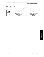
Страница 27: ... C 27 DIP switch table The DIP switches are located under the faceplate of the controller DIP SWITCH ADJUSTMENTS DIP SWITCH ON OFF 1 Parameters are locked Parameters are unlocked 2 Temperature Unit Celsius Temperature Unit Fahrenheit ...

Страница 28: ...JD N2 INDEX WARRANTY JD N2 Section D 28 INDEX WARRANTY JD N2 SECTION D ...

Страница 29: ...ical Power Backup Wiring 11 Typical Alarm Connection Wiring 12 Powering Up Procedure 13 Verify all Connections 13 Hermetically Close the JD N2 13 Put the power on 13 Secure the front panel with a lock 13 Downloading the Configuration 14 Uploading the Configuration 15 JD N2 Compatible Probes 16 Specifications 17 Troubleshooting 18 TABLE OF FIGURES FIGURE NO 1 Mounting Position and Devices 9 FIGURE ...

Страница 30: ...ut Table 22 Equipment 22 Configuration Versions 22 Ventilation System Overview 23 Parameter Description 24 Room Temperature 24 Target Temperature 24 On Idle Time 24 Manual Operation 25 Other 25 Parameter Table 26 DIP switch table 27 TABLE OF CONTENTS Section D Limited Warranty 31 ...

Страница 31: ...nts acts of God flood fire hail or any other natural disaster Any unauthorized work modification or repair on this product automatically voids the warranty and disclaims the manufacturer from all responsibility The manufacturer assumes only those obligations set forth herein excluding all other warranties or obligations This warranty stipulates that in all cases the manufacturer shall be liable on...

Страница 32: ...JD N2 VER 1 0 February 18th 2010 ...

Отзывы: