background image

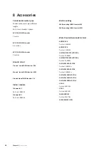
Condensation


water


pipe


Condensation water pipe,different 
lengths.
Earth circuit breaker 1-phase.

KVR


10-10

 JAMA Inverter 

1 metre

KVR


10-30


JAMA Inverter 

2.5 metres

KVR


10-60


JAMA Inverter 

5 metres

Ground


stand

Ground


stand

 JAMA Inverter M

8


Ground


stand


JAMA Inverter M

-12


Ground


stand


JAMA Inverter 

-16


Indoor


module

Tehowatti 13

Part no. 

5058535

Tehowatti 21

 Part no. 

5058536

Wall


mounting

Wall


mounting


JAMA Inverter M

8


Wall


mounting


JAMA Inverter M

12


Water


heater/Accumulator


tank

BUFFER 100

Part no. 5360118

BUFFER 200

Part no. 5360119

JASPI BUFFER 270 (GTV 270)

Part no. T000635

JASPI BUFFER 500 (GTV 500)

Part no. T000634

JASPI VLM 300 KS STAR

Part no. 5360120s

JASPI VLM 500 KS STAR

Part no. 5360121s

JASPI VLM 1000 KS STAR
JASPI VLM 1500 KS STAR
JASPI VLM 2000 KS STAR
ESC 40

Part no. M02556

ESC 41

Part no. M02691

JAMA POOL 40

Part no. M02786

JAMA SMS 40 GSM

Chapter


8


|


Accessories

38

8


Accessories

Содержание M8

Страница 1: ...Installer manual LEK LEK LEK J M Inverter M8 M12 M16 Air water heat pump...

Страница 2: ......

Страница 3: ...dium circuit Docking alternatives 21 5 Electrical connections 22 General 22 Connections 24 6 Commissioning and adjusting 30 30 30 30 31 32 Preparations Filling and venting the heating medium sys tem C...

Страница 4: ...sign or technical modifications are reserved Symbols NOTE This symbol indicates danger to machine or person Caution This symbol indicates important information about what you should observe when main...

Страница 5: ...DATA Serial number Caution Always give the product s serial number when reporting a fault Country specific information Installer manual This installer manual must be left with the customer 3 Chapter 1...

Страница 6: ...qualified person Fill in the page for information about installation data in the User manual Date Signature Notes Description System flushed System vented Particle filter Shut off and drain valve Cha...

Страница 7: ...Contact information 5 Chapter 1 Important information Kaukora Oy PL 21 Tuotekatu 11 21200 Raisio Puh 02 4374 600 E mail kaukora kaukora fi www kaukora fi...

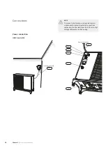
Страница 8: ...the neighbours JAMA Inverter must not be placed so that recirculation of the outdoor air can occur This causes lower output and impaired efficiency The evaporator should be sheltered from direct wind...

Страница 9: ...is used The section of the pipe that can be affected by frost must be heated by the heating cable to prevent freezing Route the pipe downward fromJAMA Inverter The outlet of the condensation water pi...

Страница 10: ...from JAMA Inverter The condensation water pipe must have a water seal to prevent air circulation in the pipe Installation area The distance between JAMA Inverter and the house wall must be at least 15...

Страница 11: ...Removing the covers JAMA Inverter M8 LEK JAMA Inverter M12 JAMA Inverter M16 LEK LEK Removing the front panel JAMA Inverter M8 LEK HQ1 9 Chapter 2 Delivery and handling...

Страница 12: ...JAMA Inverter M12 LEK HQ1 JAMA Inverter M16 LEK Removing the side panel JAMA Inverter M12 LEK JAMA Inverter M16 DATA LEK Chapter 2 Delivery and handling 10...

Страница 13: ...UB3 EP1 X1 EB11 CM 20S 63H1 LPT SM2 SM1 FM01 PWB2 PWB3 PWB1 BT12 BT15 BP4 QN2 BT3 PF3 HS1 EP2 GQ10 QN1 BP2 QM35 QM36 BP1 QN3 CH EB10 LEK DATA XL2 UB1 UB2 W1 XL1 UB3 LEK DATA PF1 PF3 11 Chapter 3 The h...

Страница 14: ...1 GQ1 GQ10 QM35 QN3 QM36 TB BP1 QN2 PWB1 PWB2 PWB3 DH UB3 BT3 BP4 PF3 BT15 EP1 EP2 HS1 BP2 BT12 X1 EB11 CM 20S 63H1 LPT SM2 SM1 FM01 CH EB10 LEK DATA XL2 UB1 UB2 W1 XL1 UB3 LEK DATA PF3 PF1 Chapter 3...

Страница 15: ...Inverter M16 LEK GQ1 DH X1 CM 63H1 CH SM2 SM1 FM01 PWB2 PWB3 PWB1 QN2 20S BT12 TB BP1 PF3 QN3 BP4 BT3 BT15 UB3 GQ10 HS1 EB10 QN1 EP2 QM36 QM35 EB11 GQ2 FM02 EP1 F LPT BP2 13 Chapter 3 The heat pump de...

Страница 16: ...LEK DATA XL2 UB1 UB2 XL1 UB3 W1 LEK DATA PF3 PF1 Chapter 3 The heat pump design 14...

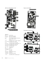
Страница 17: ...coming supply AA23 X4 Terminal block communication EB10 CH Compressor heater EB11 DH Drip tray heater F Main fuse compressor unit Fuse for external heating cable 250 mA F3 max 45 W GQ1 FM01 Fan GQ2 FM...

Страница 18: ...on EB10 CH Compressor heater EB11 DH Drip tray heater F Main fuse compressor unit Fuse for external heating cable 250 mA F3 max 45 W GQ1 FM01 Fan GQ2 FM02 Fan PWB1 PWB2 PWB3 Control board Inverter boa...

Страница 19: ...JAMA Inverter M12LEK EB11 PWB3 PWB1 EB10 AA23 FM01 TB F F3 AA23 X4 AA23 X1 DH CH GQ1 AA23 S2 LEK PWB2 17 Chapter 3 The heat pump design...

Страница 20: ...JAMA Inverter M16 LEK PWB3 PWB1 EB10 FM01 AA23 X4 DH CH GQ1 TB AA23 X1 F3 EB11 F AA23 AA23 S2 LEK PWB2 Chapter 3 The heat pump design 18...

Страница 21: ...at pump is connected so that any contaminants do not damage the components parts Pipecouplingheatingmedium circuit JAMA Inverter can be connected directly to the heating system see the section Docking...

Страница 22: ...JAMA Inverter M8 LEK DATA LEK Heat insulation JAMA Inverter M12 LEK DATA LEK Heat insulation Chapter 4 Pipe connections 20...

Страница 23: ...installed in accord ance with current regulations for all docked options See kaukora fi for more docking options Connecting accessories Instructions for connecting accessories are in the install atio...

Страница 24: ...t pump should be equipped with a separate one In coming supply must be 230 V 50Hz via distribution boards with fuses If an insulation test is to be carried out in the building disconnect the heat pump...

Страница 25: ...JAMA Inverter M12 LEK DH PWB3 CH AA23 FM01 TB F F3 X1 PWB1 AA23 X4 LEK PWB2 JAMA Inverter M16 LEK DH PWB3 CH AA23 FM01 TB F F3 X1 PWB1 AA23 X4 LEK PWB2 23 Chapter 5 Electrical connections...

Страница 26: ...ionand orsensortoexternalconnections cables must not be laid closer than 20 cm to high voltage cables when cable routing Power connection JAMA Inverter M8 LEK DATA LEK Incoming supply Power connection...

Страница 27: ...JAMA Inverter M12 LEK DATA LEK Incoming supply W1 W1 UB2 UB1 XL1 XL2 UB3 Power connection 25 Chapter 5 Electrical connections...

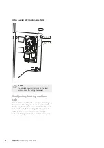
Страница 28: ...nication cable W2 provided by in staller to terminal block AA23 X4 and secure with two cable ties see image For connection of accessory KVR 10 heating cable EB14 is connected via cable grommet UB3 see...

Страница 29: ...are routed through ferrite beads EMI filters LEK JAMA Inverter M12 LEK Secure the communication cable W2 here using two cable ties JAMA Inverter M16 LEK Secure the communication cable W2 here using tw...

Страница 30: ...4 6 according to following image 5 6 4 2 3 1 WHUQDO JAMA Inverter WHUQDO KHDW FDEOH NOTE The pipe must be able to withstand the heat from the heating cable To ensure this function the accessory KVR 10...

Страница 31: ...ck X4 4 6 according to the following image Innemodul X4 GND GND B B A A GND B A AA3 WHUQDO JAMA Inverter For connection of indoor module see relevant manual on www kaukora fi Addressing via cascade co...

Страница 32: ...the venting nipple QM20 on the enclosed flexible hose and possibly the cir culation pump 40 Compressor heater JAMA Inverter is equipped with a compressor heater that heats the compressor before start...

Страница 33: ...be connected 4 Turn the isolator switch on 5 Ensure that the JAMA Inverter is connected to the power source 6 After 6 8 hours the communication cable W2 is connected to terminal block AA23 X4 7 Resta...

Страница 34: ...de Air is initially released from the hot water and venting may be necessary If bubbling sounds can be heard from the heat pump the circulation pump and radiat ors the entire system will require furth...

Страница 35: ...r adjusting hot water charging are in the installation manual for the respective indoor section See page 38 for the list of the indoor sections and ac cessories that can be used with JAMA Inverter 33...

Страница 36: ...o the hot water heater Large hot water consumption Wait until the hot water has heated up Incorrect settings in the JAMA indoor module See the manual for the indoor module Low room temperature Closed...

Страница 37: ...Connection to card PWB1 Sensor placement JAMA Inverter M8 LEK EB11 EB10 GQ1 PWB1 BP1 QN2 QN3 QN1 BP2 SM1 SM2 LPT FM01 DH 20S CH 63H1 35 Chapter 7 Disturbances in comfort...

Страница 38: ...erature sensor hot gas BT15 Temperature sensor fluid pipe BT16 Tho Temperature sensor heat exchanger 1 R1 BT17 Tho S Temperature sensor suction gas BT28 Tho A Temperature sensor ambient EB10 CH Compre...

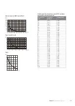
Страница 39: ...VDC Resistance kOhm Temperature C 3 256 351 0 40 3 240 251 6 35 3 218 182 5 30 3 189 133 8 25 3 150 99 22 20 3 105 74 32 15 3 047 56 20 10 2 976 42 89 5 2 889 33 02 0 2 789 25 61 5 2 673 20 02 10 2 5...

Страница 40: ...ehowatti 21 Part no 5058536 Wall mounting Wall mounting JAMA Inverter M8 Wall mounting JAMA Inverter M12 Water heater Accumulator tank BUFFER 100 Part no 5360118 BUFFER 200 Part no 5360119 JASPI BUFFE...

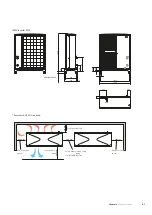
Страница 41: ...400 670 100 365 225 422 965 1035 95 15 90 40 Adjustable 40 50 Accessory KVR 10 is required JAMA Inverter M12 50 255 St llbar 40 50 955 243 512 110 395 265 50 452 1075 1145 108 40 14 85 Adjustable 40...

Страница 42: ...Accessory KVR 10 is required 150 mm Fritt utrymme bakom Min avst nd 600 mm 3000 mm 400 mm 600mm Minimalt fritt utrymme Minimalt fritt utrymme Fritt utrymme Free space behind Free space in front Minimu...

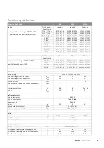
Страница 43: ...bricks differences in ground level etc and should therefore only be seen as guide values JAMAInverteradjuststhefanspeeddependingonthe ambient temperature and evaporation temperature 2 m 6 m 10 m 2 m...

Страница 44: ...3 50 27 18 C Output data according to EN14511 T5K Specified supplied power EER 13 04 4 53 2 88 9 45 3 41 2 77 7 10 2 65 2 68 35 7 C 15 70 5 04 3 12 11 20 3 58 3 12 9 19 2 98 3 08 35 18 C Electrical d...

Страница 45: ...Weight excl packaging Miscellaneous IP 24 Enclosure class dark grey Colour 1 Max permitted impedance in the mains connected point in accordance with EN 61000 3 11 Start currents can cause short voltag...

Страница 46: ...rature Supply temperature Return temp During shorter time it is allowed to have lower working temperatures on the water side e g during start up Working range compressor operation cooling JAMA Inverte...

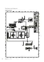
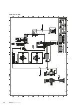
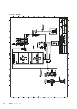
Страница 47: ...Electrical circuit diagram JAMA Inverter M8 Chapter 9 Technical data 46 Kaukora Oy...

Страница 48: ...INV PWB2 OR GR 1 F P BK BK 4A 2 3 Tho P BP1 63H1 BT14 Tho D BT16 Tho R1 BT17 Tho S BT28 Tho A BP2 LPT 20S QN2 EB10 CH EB11 DH 47 Chapter 9 Technical data...

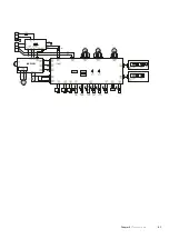
Страница 49: ...JAMA Inverter 12 Chapter 9 Technical data 48 Kaukora Oy...

Страница 50: ...Y 2 WH 1 WH RD BK CNIP Y Tho P BK BK OR CNFAN1 WH BL 7 BR 6 WH 5 4 RD 1 CNH BR BP1 63H1 Two fan unit only Two fan unit only BK BK CNS RD CNR WH CNF BK BL BL EB10 CH BR BR BT14 Tho D BK BK BT16 Tho R1...

Страница 51: ...JAMA Inverter 16 Chapter 9 Technical data 50 Kaukora Oy...

Страница 52: ...WH 1 RD CNEEV2 RD CNPS RD CNB RD 6 BL 4 OR 3 Y 2 WH 1 WH RD BK CNIP Y Tho P BK BK OR CNFAN1 WH BL 7 BR 6 WH 5 4 RD 1 CNH BR BP1 63H1 Two fan unit only BK BK CNS RD CNR WH CNF BK BL BL EB10 CH BR BR B...

Страница 53: ...n to rear side standard or underneath al ternative 24 External heating cable KVR 10 28 F Filling and venting the heating medium system 30 I Important information 2 Safety information 2 Inspection of t...

Страница 54: ......

Страница 55: ...Kaukora Oy PL 21 Tuotekatu 11 21200 Raisio Puh 02 4374 600 E mail kaukora kaukora fi www kaukora fi...
Отзывы: