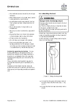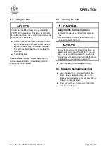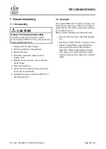
M
AINTENANCE
8.2. Model for determining the actual use
The decisive factors for the type of operation are the
load spectrums with different cubic averages
k
.
The load spectrum indicates to what extent a driving
mechanism, or part of one, is subjected to its maxi-
mum stress or whether it is only subjected to lower
stresses. The cubic mean value (factor of the load
spectrum) is calculated using the following formula:
k
=
3
p
(
β
1
+
γ
)
3
·
t
1
+ (
β
2
+
γ
)
3
·
t
2
+
. . .
+
γ
3
·
t
∆
Darin bedeuten:
β
=
P ayload or ultimate load
Load capacity
γ
=
Dead load
Load capacity
k
=
Operating time with payload or partial load and dead load
T otal operating time
t
∆
=
Operating time with dead load
T otal operating time
The FEM 9.511 rule differentiates between four load
spectrums, which are identified by the definitions
and by the ranges of the cubic averages
k
. This
classification complies with ISO 4301/1.
The formula given for the cubic average
k
does not
take the weight of the harness into account. This is
permissible if the ratio
W eight of the harness
Load capacity
≤
0
,
05
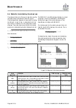
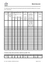
To determine the mode of operation for calculating
the partial operating times (actual operating time),
the following load spectrum diagrams can also be
used.
Figure 12: Diagram of the load spectrums
Load
spectrum
Definition
Cubic average
Collective load
factor
L1
(light)
Driving mechanisms or parts thereof, which are only subject
to the maximum stress in exceptional circumstances and are
only subject to very low stresses continuously.
k
≤
0
,
50
k
m
=
k
3
= 0
,
125
L2
(medium)
Driving mechanisms or parts thereof, which are subject to
the maximum stress fairly often and are only subject to low
stresses continuously.
0
,
50
< k
≤
0
,
63
k
m
=
k
3
= 0
,
25
L3
(heavy)
Driving mechanisms or parts thereof, which are often sub-
ject to the maximum stress and are continuously subject to
average stresses.
0
,
63
< k
≤
0
,
80
k
m
=
k
3
= 0
,
5
L4
(very heavy)
Driving mechanisms or parts thereof, which are regularly
subject to the maximum stress of adjacent stresses.
0
,
80
< k
≤
1
,
00
k
m
=
k
3
= 1
Page
42
of 64
Doc.-No.: VA049318-10-OM-EN-0319-64-2


