TECHNICAL SECTION
[21]
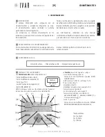
For help see ‘NAVIGATION MAP’ on pg. 22
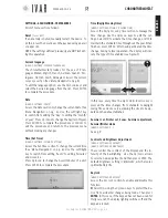
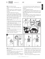
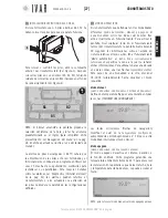
2) EDITING A PARAMETER (see Table-3)
Adjust the front selector in the
‘+’
or
‘-’
direction to edit the
value of the previously selected, indicated by the fixed led
light. Then maintain the selector in the
SELECT
position for
5 seconds to confirm the selected value. The flashing of
LEDs 3 and 4 indicates the successful completion of the
procedure and the return to the parameters list. Therefore,
release the key. A period of 60 seconds of inactivity, without
making the change to the parameter being set, completes
the programming.
NOTE:
the options setup can be run, even if the actuator has
not yet been associated with a chronothermostat.
PARAMETERS
1) Service
• A =
Disassociation from chronothermostat
• B =
Actuator reset
• C =
No action (Default)
2) Anti-condensation
(See ‘Anti-condensation function’ on pg. 23.)
3) Hysteresis
This parameter is enabled only in ON/OFF operation and rep-
resents the positive/negative deviation from the set point,
useful for determining the closure/opening of the valve.
- Ist.
SETPOINT
OPEN
CLOSED
OPEN
Temper-
ature
Time
+ Ist.
4) Pmax
Defines the proportional working band of the actuator.
5) Cp (Corrective position of the actuator)
Represents the theoretical point of valve closure (See
graph). Given the actuator effectively goes into overtravel
due to the elasticity of the rubber seal, the Cp allows the im-
mediate correction of this positioning in the opening phase.
Cp + Pmax
0*
3
12
Theoretical valve
closure point
Pmax=9
Cp=3
overtravel
* The ‘0’ closing position is found in a self-adapting manner
by the actuator.
6) Kp (Proportional coefficient)
The shifting of the actuator is proportional to the differ-
ence between the temperature required temperature and
the actual temperature. When Kp is increased smaller shifts
are obtained, while reducing Kp larger shifts are obtained.
Kp=0.01 (minimum value) results in ON/OFF operation.
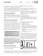
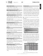
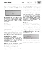
Automatic opening/closing operation
A)
To fully open the actuator, maintain the front selector in po-
sition
‘+‘
until Led 3 flashes for the first time, which occurs af-
ter 5 seconds. Release the button after this signal.
Signal T1*
indicates opening has occurred (See ‘Signals’ on pg. 20).
Then press the selector in the
SELECT
position until
Signal
A*
, which occurs after 5 seconds. Release the button after
this signal, completing the operation.
B)
To fully close the actuator, maintain the front selector in
position
‘-‘
until Led 4 flashes for the first time, which oc-
curs after 5 seconds. Release the button after this signal.
Signal T2*
indicates closure has occurred.
Then press the selector in the
SELECT
position until
Signal
A*
, which occurs after 5 seconds. Release the button after
this signal, completing the operation.
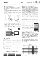
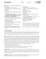
Radio signal test
To check the quality of an actuator’s radio signal, maintain
the front selector in the
SELECT
position until the led indica-
tor’s luminous signal appears, after 30 seconds. The quality
level is indicated in Table-4.
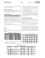
TABLE 4: RADIO SIGNAL TEST
Signal quality
à
2
(max)
1
0
(absent)
Led 1
µ
µ
µ
Led 2
µ
µ
µ
Led 3
µ
µ
µ
Led 4
µ
µ
µ
Led 5
µ
µ
µ
Led 6
µ
µ
µ
( NOTE:
µ
= Led on )
300546US-10-14
ENGLISH
Содержание Equicalor
Страница 46: ...300546US 10 14 ...
Страница 47: ...300546US 10 14 ...
Страница 48: ...300546US 10 14 W W W I V A R U S C O M EQUICALOR IT GB DE FR ES DE BE CZ NO ...

