ACTUATOR
[14]
FEATURES OF THE ACTUATOR
Each actuator (sold individually; provided separately
from the chronothermostat) physically controls the
radiator on which it is installed, guided by the chrono-
thermostat.
If you wish to improve the comfort level of a particu-
lar room or part thereof, there is also the possibility of
controlling each actuator immediately. In this way, maxi-
mum yield is obtained with accuracy and simplicity.
CONTENTS OF THE PACKAGE
• Actuator
• Utility key
• Stylus alkaline batteries
• Instructions sheet
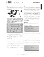
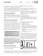
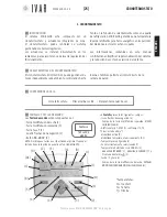
LED INDICATOR AND FRONT SELECTOR SWITCH
The actuator controls are found on the front side of the
device. They consist of:
•
Led Indicator
[LED from 1 to 6]
•
Front selector
[control key]
The front selector key operates in three positions:
A)
Position ‘+’
(HIGH)
B)
Position ‘SELECT’
(pressing the key)
C)
Position ‘-‘
(LOW)
LED 1
LED 2
LED 3
LED 4
LED 5
LED 6
FRONT
SELECTOR
2. ATTUATORE
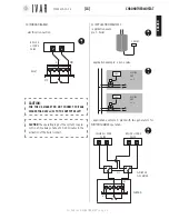
WARNINGS
1 .
During actuator installation, it is recommended that you
protect the toothed ring nut using a rag when tightening.
2 .
When working with the actuator make sure it does
not come into contact with water and do not expose it to
high levels of humidity.
3 .
The actuator options setup procedure should be
preferably be performed by the installer.
4 .
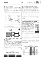
It is important to verify that the batteries are work-
ing properly to prevent the heating/cooling system from
shutting down due to a lack of power to the actuator.
5 .
Observe the following directions for using the bat-
teries: when it is time to dispose of them, place them
separately into the appropriate recycling container;
follow the installation instructions provided; avoid con-
necting the metal poles that are in contact with the
batteries in order to prevent a short circuit; always use
the type of batteries specified in this manual; do not
mix different batteries, old and new batteries or alkaline
batteries with standard or zinc coal batteries; the use
of rechargeable batteries results in less operating au-
tonomy when compared to non-rechargeable batteries.
6.
If the device causes interference with other electrical
equipment, immediately remove them from the area.
7 .
Do not dis-
pose of the
device in the
environment at
the end of its life
cycle. Dispose
of the device in
compliance with
current legisla-
tion.
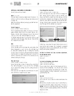
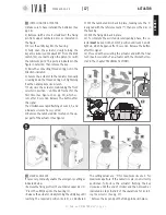
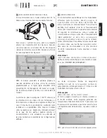
8 .
Follow the
directions in Fig-
ure-12 to posi-
tion the actuator.
ACTUATOR
CONTROLS
11
B*
11
A
11
D*
11
C*
FIG.
12
FIG.
11
B
PRESS
C
PUSH
DOWN-
WARDS
A
PUSH
UPWARDS
* See ‘Remote sensor’ on pg. 16
300546US-10-14
Содержание Equicalor
Страница 46: ...300546US 10 14 ...
Страница 47: ...300546US 10 14 ...
Страница 48: ...300546US 10 14 W W W I V A R U S C O M EQUICALOR IT GB DE FR ES DE BE CZ NO ...


