background image

TECHNICAL SECTION

[18]

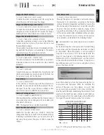
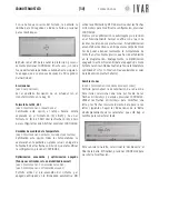
List of example alarms:

---Date------Time------ID----ERR---

10/02/11  

07.00.00

  Ch00  

L BATT

03/02/08  

11.10.21

  Ac02  

ERR MO

19/01/12  

09.05.30

  Ac03  

L SIGN

12/01/10  

05.22.59

  Ac05  

ERR TE

GENERAL OPERATION NOTES

The ambient temperature is detected directly on the 
chrono for Zone 1 (Master) and on the actuators in Zones 
2-8 (Slave). A patented algorithm allows correcting the 
proximity effect that originates in Zones 2-8 due to the 
proximity between the sensor and the heat source.

3. TECHNICAL SECTION


3.1 

CHRONOTHERMOSTAT – SETUP

Access the Advanced Settings section (See ‘Menu Navi-
gation’ on pg. 6 for information about the control 
keys) to adjust plant options depending on the specific 
characteristics of the building 

(

MENU

à

SETTINGS

à

AD-

VANCED SETINGS...


this path will be indicated in this chap-

ter by an asterisk for the purpose of brevity)

During the access phase, respond to the system prompt 
by selecting 

ENTER

 to proceed. The ‘Advanced Settings’ 

are listed below.

Limits

[*

à

PLANT

à

LIMITS

à

WINTER]

[*

à

PLANT

à

LIMITS

à

SUMMER]

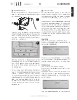
To determine the maximum and minimum value of 
each of the 6 temperature ranges that make up the 
Winter set and Summer set, go to the 

Limits

 section 

(For more information about the SETS, see 

Managing 

the temperature sets

 on pg. 23). Select a value to 

edit within the setting group chosen (Summer or Win-
ter) and press 

ENTER

. Using the 

Up/down

 arrows, adjust 

the value (maximum and minimum) corresponding to 
Comfort-T1, Saving-T2 or Limit-T3. Then press 

ENTER

.

Pre-activation (Max start up and shutdown anticipa-
tion)

[*

à

PLANT

à

PRE-ACTIVATION

à

MAX ANTICIPATION OF START UP]

[*

à

PLANT

à

PRE-ACTIVATION

à

MAX ANTICIPAT. OF SHUTDOWN]

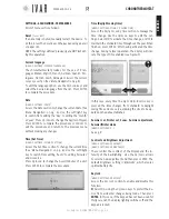
Defines the maximum time limit that is calculated au-
tomatically by the chronothermostat for optimized sys-
tem start up/shutdown (MAX ANTICIPATION OF START UP/
MAX ANTICIPATION OF SHUTDOWN).
The time is expressed in minutes and can be changed 
at increments of 1 minute. Use the 

Up/down

 arrows to 

adjust and then press 

ENTER

.

Pre-activation (Prestart savings reduction)

[*

à

PLANT

à

PRE-ACTIVATION

à

PRESTART SAVINGS REDUCTION]

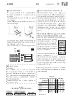
Modify this value to define the temperature drop 
value obtained exiting the Comfort band when ‘SHUT-
DOWN OPTIMIZATION’ is enabled. This value is set by

default to 1 °F. Use 
the 

Up/down

 arrows 

to adjust and then 
press 

ENTER

.

Pre-activation (Comfort prestart index)

[*

à

PLANT

à

PRE-ACTIVATIONS

à

COMFORT PRESTART INDEX]

Adjust this value 
to set the prestart 
comfort 

range  

which the sys-
tem applies to the 
function ‘START 
UP OPTIMIZATION’. 
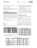
The Index is set to 30 by default (10 = minimum, 60 = 
maximum). A lower value minimizes the prestart, while 
a greater value accentuates it. Use the 

Up/down

 arrows 

to edit and then press 

ENTER

.

Diagnostic (Stored Delta TPR)

[*

à

PLANT

à

DIAGNOSTICS

à

STORED DELTA TPR]

Access to view the Delta TPR parameter, which is involved 
in the controlling the zones. Press 

EXIT

 to go back.

Diagnostics (Alarm History)

[*

à

PLANT

à

DIAGNOSTICS

à

ALARM HISTORY]

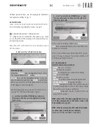
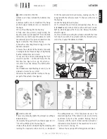
Access to view the chronological list of alarms (pre-
sent and past) reported by the system. Press 

EXIT

 to 

go back. The list indicates the date and time in which 
the problem was 
detected, the ID 
(identifier) of the 
involved device 
and the type of 
problem (ERR). 
The ID speci-
fies the type of 
device the alarm concerns (CH=chronothermostat, 
Ac=actuator) as well as its identification number. The 
possible alarms (ERR) may include:
1) L BATT = Batteries discharged
2) L SIGN = Low radio communication capacity
3) ERR TE = Built-in or remote temperature sensor

failure (if installed).

4) ERR MO = Electric motor failure
NOTE: the errors 1, 2 and 3 are also indicated on the 
actuators (See ‘Signals‘ on pg. 20).

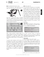
Temperature

T1

Time

0.5
1.0
1.5

T2

Temperature

T1

Time

60

30

10

T2

300546US-10-14

Содержание Equicalor

Страница 1: ...R DC 1010 USER S GUIDE Wireless system for independent management of thermal regulation MANUAL DE INSTRUCCIONES Sistema inalámbrico para la automa tización de la termorregulación 300546US 10 14 P A T E N T E D ...

Страница 2: ...e in a position exposed to good air circulation at 5 ft above the floor See Typical placement of device on pg 10 3 Chronothermostat wall installation Secure the chronothermostat in the desired position and con nect it to the boiler Refer to Wall installation on pg 11 CAUTION Make sure to cut out the mains voltage to the electrical system before carry out this procedure 4 Insert the batteries in th...

Страница 3: ... 5 Reset key 2 Four navigation keys 3 OK MODE button 4 NOTE If the key lock is not active simply touch keypad and it will become operational CONTROL KEYS DISPLAY temperature T1 T comfort T2 T saving T3 T limit L I 3 4 1 5 B M C 2 A H G F D E D1 The Display has the following fields Navigation keys icon A Left multi function key field MENU EXIT CANCEL B 7 DAYS Schedule Graph C T1 T2 T3 see note belo...

Страница 4: ...egulations and with the mains voltage switched off 7 In the event of a problem s a List of Alarms appears when the display is switched on See the following paragraphs CHRONOTHERMOSTAT CONDITIONS OF WARRANTY I V A R S p A is insured against damage caused to third parties due to product manufacturing defects in accord ance with the terms and limits set out in Legislative De cree 206 2005 The maximum...

Страница 5: ...ERATING MODES The Chronothermostat operates in three different modes Automatic Manual and OFF The Enabled Mode icon indicates which of the three modes is currently enabled To activate the display simply touch any key During normal chronothermostat operation the display will show the information regarding the status of the system relative to the mode currently enabled for 30 seconds When operating ...

Страница 6: ...ht multi function key to access 2 scroll the list with the UP DOWN keys to select Start up optimization and then press the right mul ti function key to edit In the various editing options the Multi function keys allow proceeding step by step until these pro cedures are complete Refer to the following list Note that after 30 sec onds if no key is pressed the system switches off the display exiting ...

Страница 7: ...ER In this case if the keypad has not been used for thirty seconds the display lighting switches off and the keypad is locked FIG 3 SETTINGS ASSOCIATIONS PREFERENCES A list of menu sections follows Reset reset KEY If an anomaly is noted manually restart the device To do this press the Reset key on the keypad using a pencil or paper clip NOTE the settings defined previously are NOT lost dur ing thi...

Страница 8: ...n the Character scroll bar lo cated under the name to compose text 2 Select OFF to cancel the protection and then press ENTER In this case the display will light up at each touch of the keypad until the next shutdown which occurs af ter 30 seconds of inactivity Associations MENUàASSOCIATIONS Refer to the paragraph Association of an actuator with the chronothermostat on pg 19 Time format 12 24 MENU...

Страница 9: ... lines of the graph see Figure 4 and Managing the temperature sets on pg 23 Access the Winter Set section or the Summer Set sec tion depending on the mode you wish to work in see Summer Winter Mode Use the Up down to highlight the required field and then press ENTER Using the Up down arrows select Set comfort to cus tomize temperature T1 Set saving for T2 or Set limit for T3 By appropriately adjus...

Страница 10: ...cting ENTER and then EDIT Re peat the operation until a typical week has been defined Summer adjustment Weekly Schedule MENUàSETTINGSàSUMMER ADJUSTMENT When the SUMMER mode is enabled access Summer Ad justment to define the weekly schedule Refer to the similar procedure described in the previous paragraph Zones Manual for 1 hour and then Auto Manual Mode MENUàMODEàMAN MODEàMANUAL FOR 1 HOUR MENUàM...

Страница 11: ...contact cables through the slot S1 Connect the power cables to the terminal in posi tions NO and C as indicated at the bottom of the lid See the Wiring diagram on pg 13 for further instructions Lastly put the lid back on to close the box and then tighten the screws 1 S1 x2 UNSCREW S 2 1 S1 3 3 Place the device against the wall and secure it as shown 3 The possible options are as follows A box moun...

Страница 12: ...o the following two conditions 1 this device may not cause harmful interference and 2 this device must accept any interference received including interfer ence that may cause undesired operation NOTE this equipment has been tested and found to comply with the limits for a Class B digital device pursuant to Part 15 of the FCC Rules These limits are designed to provide reasonable protection against ...

Страница 13: ...n example 3 plant with two generators for WINTER SUMMER operation FIG 7 FIG 8 FIG 9 CHRONO 0 WINTER 1 SUMMER 0 1 C NO NC BOILER or ZONE VALVE CHILLER or ZONE VALVE FIG 10 CAUTION the operating logic of the system may re sult in a time delay of about 15 20 minutes in the activation of the boiler contact BOILER or ZONE VALVE RELAY NO NC C CAUTION FOR THE US MARKET DO NOT CONNECT VOLTAGE HIGHER THAN ...

Страница 14: ...ls of humidity 3 The actuator options setup procedure should be preferably be performed by the installer 4 It is important to verify that the batteries are work ing properly to prevent the heating cooling system from shutting down due to a lack of power to the actuator 5 Observe the following directions for using the bat teries when it is time to dispose of them place them separately into the appr...

Страница 15: ...sonable protection against harmful interference in a residential installation This equipment generates uses and can radiate radio frequency energy and if not installed and used in accordance with the instructions may cause harmful interference to radio communications However there is no guarantee that interference will not occur in a particular installation If this equipment does cause harmful int...

Страница 16: ...actuator can go from approx 56 F to 68 F After having set the desired temperature see Table 1b a 5 second wait completes the procedure according to the new setting Signal µ Led on Led 1 µ Led 2 µ Led 3 µ Led 4 µ Led 5 µ Led 6 µ OPEN THIS WAY FIG 13 BATTERY REPLACEMENT The actuator requires 3 AA 1 5 V Alkaline batteries The batteries must be inserted in order to operate the equipment 1 To replace t...

Страница 17: ...s the utility key into the housing 4 Fully open the actuator slowly turning the key anti clockwise until about 45 from the limit switch 4a in order to align the piston 4c with the minimum point This point is indicated in the figure in detail 4d Then remove the key 5 Raise the connecting threaded ring nut in the direction indicated 6 Secure the actuator to the radiator manually screwing down the th...

Страница 18: ...mized sys tem start up shutdown MAX ANTICIPATION OF START UP MAX ANTICIPATION OF SHUTDOWN The time is expressed in minutes and can be changed at increments of 1 minute Use the Up down arrows to adjust and then press ENTER Pre activation Prestart savings reduction àPLANTàPRE ACTIVATIONàPRESTART SAVINGS REDUCTION Modify this value to define the temperature drop value obtained exiting the Comfort ban...

Страница 19: ...to delete the changes that have been made to the advanced settings A warning is prompted before you can proceed Select ON using the Up arrow Then press ENTER to make the change Total device reset àPLANTàTOTAL DEVICE RESET Through this option it is possible to restore the chrono thermostat to its initial state according to the factory settings After providing further confirmation restore the time b...

Страница 20: ...T rapid simultaneous flashing of LEDs 1 2 and 3 repeated 3 times T2 CLOSING TEST rapid simultaneous flashing of LEDs 4 5 and 6 repeated 3 times ANOMALY in case of active alarms the indicator com municates the following warnings at each touch of the front selector L BATT Led 3 and 4 on L SIGN Led 2 and 5 on ERR TE Led 1 and 6 on See Diagnostics Alarm History on pg 18 Options setup selection and edi...

Страница 21: ...oretical valve closure point Pmax 9 Cp 3 overtravel The 0 closing position is found in a self adapting manner by the actuator 6 Kp Proportional coefficient The shifting of the actuator is proportional to the differ ence between the temperature required temperature and the actual temperature When Kp is increased smaller shifts are obtained while reducing Kp larger shifts are obtained Kp 0 01 minimu...

Страница 22: ...ER SUMMER MODE DATE TIME TIME FORMAT TEMPERAT MEASUREMENT UNITS CONTRAST BRIGHTNESS START UP OPTIMIZATION SHUTDOWN OPTIMIZATION SET ZONE NAMES MODE SETTINGS ASSOCIATIONS PREFERENCES MANUAL MODE AUTOMATIC MODE SHUTDOWN MODE SET TIME DAYLIGHT S TIME SET WINTER COMFORT SET WINTER SAVING SET WINTER LIMIT SET SUMMER COMFORT SET SUMMER SAVING SET SUMMER LIMIT ENABLE MANUAL MODE MAN FOR 1 HOUR MAN FOR 2 ...

Страница 23: ... to redefine the maxi mum and minimum values for each of the 6 tempera ture ranges For example 1 Access MENUàSETTINGSàADVANCED SETTINGSàPLANTà LIMITSàWINTERàMINIMUM WINTER COMFORT TEMP and set a value of 68 F Then press ENTER 2 Access MENUàSETTINGSàADVANCED SETTINGSàPLANTà LIMITSàWINTERàMAXIMUM WINTER COMFORT TEMP and set a value of 80 F Then press ENTER In this way a COMFORT range 12 F of extensi...

Страница 24: ...cir culación de aire a 5 ft del suelo Ver Posicionamiento típico del aparato en la pag 32 3b Instalar el cronotermostato en la pared Fijar el cronotermostato en la posición establecida y ejecutar la conexión a la caldera Ver Instalación a la pared en la pag 33 ATENCIÓN Asegurarse de excluir la tensión de red del sistema eléctrico antes de realizar dicho procedimiento 4 Colocar las pilas en el cron...

Страница 25: ...flechas de navegación 3 Botón OK MODE 4 NOTA Si el bloqueo teclas no está activado el primer toque del teclado tiene la función de ponerlo en funcionamiento TECLAS DE MANDO PANTALLA temperaturas T1 T confort T2 T ahorro T3 T límite L I 3 4 1 5 B M C 2 A H G F D E D1 La Pantalla presenta los siguientes campos Icono flechas de navegación A Campo de la tecla multifunción izquierda MENÚ SALIR ANULAR B...

Страница 26: ...de las alarmas aparece al encenderse la pantalla en caso de posibles anomalías Ver el apartado siguiente CONDICIONES DE GARANTÍA DEL CRONOTERMOSTATO I V A R S P A está asegurada por daños ocasionados a terceros por defecto de fabricación constatado de los productos en los términos y límites enunciado en el Decreto Legislativo 206 2005 La cobertura máxima de seguro de 3 000 0000 por siniestro y por...

Страница 27: ... puede trabajar en tres modalidades diferentes modo Automático Manual y Apagado El icono Modalidad activa nos indica cuál de éstas tres está actualmente en funcionamiento Para activar la pantalla tocar cualquier tecla En el funcionamiento normal del cronotermostato la pantalla ilustra durante 30 segundos las informaciones sobre el estado del sistema relativas al modo activo En el funcionamiento Mo...

Страница 28: ...BA ABAJO para seleccionar Optimización encendido y presionar la Te cla multifunción derecha para iniciar la modificación En las diferentes operaciones de modificación de las opciones las Teclas multifunción permiten proceder paso a paso para completar dichos procedimientos Ver la lista siguiente Se aconseja saber que si no se opera en los mandos por más de 30 segundos el sistema apaga la pantalla ...

Страница 29: ...lado por 30 segundos la pantalla suspende la iluminación y el teclado se bloquea FIG 3 CONFIGURACIONES ASOCIACIONES PREFERENCIAS Sigue una lista de las secciones del menú Reset TECLA reset Si se verifica un comportamiento atípico volver a encender el dispositivo Para ello presionar con un lápiz o un ganchito el botón Reset en el teclado de mando NOTA con esta operación NO se pierden las configurac...

Страница 30: ...s de la Barra de desplazamiento de los caracteres que está bajo el nombre para redactar el texto 2 Seleccionar OFF para anular la protección y sucesi vamente presionar CONFIRMAR En este caso con cada toque del teclado la pantalla se ilumina hasta el siguien te apagado que se produce después de 30 segundos de inactividad Asociaciones MENÚàASOCIACIONES Ver el apartado Asociación de un actuador con e...

Страница 31: ...FIGURACIONESàPROGRAMACIÓN VERANO Para definir las 3 franjas de temperatura de división del Gráfico Horario 7 DÍAS realizar lo que se indica a continuación las 3 franjas están representadas por las líneas horizontales del gráfico ver Figura 4 y Gestión de los set de temperatura de la pag 45 Acceder a la sección Programación invierno o a la sección Programación verano según la modalidad que se quier...

Страница 32: ...e nuevo MODIFICAR Repetir la operación hasta definir una semana tipo Regulación verano Programación semanal MENÚàCONFIGURACIONESàREGULACIÓN VERANO Cuando la modalidad VERANO está activada acceder a Regulación verano para definir la programación semanal Ver el procedimiento análogo descrito en el apartado anterior Zonas Manual para 1 hora y después Auto Modo Manual MENÚàMODALIDADàMODO MAN àMANUAL 1...

Страница 33: ...a ranura S1 los cables del contac to caldera Efectuar la conexión eléctrica de los cables en el borne en las posiciones NO y C como se indica en el fondo de la cobertura Ver el Esquema de las conexiones de la pag 35 para mayores indicaciones Por último volver a colocar la caja para cerrarla enroscando los tornillos 1 S1 x2 DESENROSCAR S 2 1 S1 3 3 Posicionar el aparato de pared ase gurándolo como ...

Страница 34: ...ir interferencias perjudiciales 2 este dispositivo debe tolerar cualquier interferencia recibida incluidas aquellas interferencias que pueden provocar un funcionamiento no deseado NOTE a partir de las pruebas a las que ha sido sometido este equipo se concluye que cumple con los límites para un dispositivo digital de Clase B en conformidad con la Parte 15 de las Normas de la FCC Estos límites están...

Страница 35: ...CONEXIONES conexión eléctrica ejemplo de aplicación 3 instalaciones con dos genera dores para el funcionamiento VERANO INVIERNO FIG 8 FIG 9 CRONO 0 INVIERNO 1 VERANO 0 1 C NO NC CALDERA o VÁLVU LA DE ZONA CHILLER o VÁLVULA DE ZONA FIG 10 ATENCIÓN La logica de funcionamento del siste ma puede aplazar la activación de contacto calde ra de aproximadamente 15 20 minutos AVISO PARA EL MERCADO DE EE UU ...

Страница 36: ...cedimiento de configuración de las opciones del actuador debe ser encomendado al instalador 4 Es importante verificar la plena eficiencia de las pilas para prevenir la parada del sistema de calefacción refrigeración debidos a la ausencia de alimentación del actuador En condiciones normales de funcionamiento del dispositivo y de buena conservación de las pilas durante el tiempo de almacenamiento la...

Страница 37: ...C Estos límites están destinados a proporcionar una protección razona ble contra las interferencias perjudiciales en una insta lación de tipo residencial Este equipo genera usa y pue de emitir energía de radiofrecuencias y si no se instala y utiliza de acuerdo con las instrucciones puede provocar interferencias perjudiciales en las comunicaciones vía radio Sin embargo no puede garantizarse que no ...

Страница 38: ...dor puede ir de aprox 56 F a 68 F Después de haber configurado la temperatura deseada ver Tabla 1b una espera de 5 segundos concluye el procedimiento según la nueva configuración Señal µ Led encendido Led 1 µ Led 2 µ Led 3 µ Led 4 µ Led 5 µ Led 6 µ ABRIR FIG 13 INSTALACIÓN SUSTITUCIÓN DE LAS PILAS El actuador usa n 3 pilas alcalinas AA 1 5V Se deben colocar las pilas para que el aparato funcione 1...

Страница 39: ...resionar en el alojamiento la llave de utilidad 4 Poner el actuador en apertura total girando lentamente la llave en sentido antihorario hasta llegar a unos 45 del final de carrera 4a para alinear el pistón 4c con el punto de mínimo Di cho punto está indicado en la figura en el detalle 4d Después quitar la llave 5 Alzar el zuncho roscado de conexión en el sen tido indicado 6 Asegurar el actuador a...

Страница 40: ... del sistema OPTIMIZACIÓN ENCENDIDO OPTIMI ZACIÓN APAGADO El tiempo está expresado en minutos y se puede modificar con un paso de 1 minuto Usar las flechas Arriba abajo para regular presionar CONFIRMAR Preactivaciones Pre start ahorro reducido àINSTALACIÓNàPREACTIVACIONESàPRE START AHORRO REDUCIDO Regular este valor para definir la entidad de la caída de tem peratura que se obtiene a la salida de ...

Страница 41: ...er continuar Seleccionar ON utilizando la flecha Arriba Después presionar CONFIRMAR para ejecutar el mando Reset total cronotermostato àINSTALACIÓNàRESET TOTAL CRONOTERMOSTATO Por medio de esta opción se puede reconducir totalmente el cronotermostato al estado inicial según las configuraciones de fábrica Después de haber dado otra confirmación restablecer las franjas horarias y todos los parámetro...

Страница 42: ...ector frontal los siguien tes avisos L BATT Led 3 y 4 encendidos L SIGN Led 2 y 5 encendidos ERR TE Led 1 y 6 encendidos Ver Diagnóstico Historial de alarmas de la pág 40 Setup de las opciones selección y modificación 1 SELECCIÓN DE UN PARÁMETRO ver Tabla 2 Para iniciar la configuración de los parámetros mantener el selector en posición SELECCIONAR hasta que se iluminen los Led 1 y 6 que se produc...

Страница 43: ...onalidad El desplazamiento del actuador es proporcional a la dife rencia entre la temperatura requerida y aquella efectiva Aumentando Kp se producen desplazamientos más pe queños reduciendo Kp se obtienen desplazamientos más grandes Kp 0 01 valor mínimo implica funcionamiento ON OFF Operación automática de apertura cierre A Poner el actuador en apertura total manteniendo el se lector frontal del a...

Страница 44: ...REGULACIΟN VERANO MODALIDAD VERANO INVIERNO FECHA HORA FORMATO HORA UNIDADES DE MEDIDA TEMPERATURA CONTRASTE LUMINOSIDAD OPTIMIZACIÓN ENCENDIDO OPTIMIZACIÓN APAGADO CONFIGURACIÓN NOMBRES ZONAS MODALIDAD CONFIGURACIONES ASOCIACIONES PREFERENCIAS MODO MANUAL MODO AUTOMÁTICO MODO APAGADO CONFIGURAR HORA HORA LEGAL CONFORT INVERNAL AHORRO INVERNAL LÍMITE INVERNAL CONFORT VERANO RISPARMIO ESTIVO LÍMITE...

Страница 45: ...uera necesario redefinir el valor máximo y mínimo de cada uno de los 6 campos de temperatura Por ejemplo 1 Acceder a MENUàCONFIGURACIONESàCONFIGURACIONES AVANZADASàINSTALACIÓNàLÍMITESàINVIERNOàTEMP CON FORT MINIMA INVERNAL y definir un valor de 68 F Después presionar CONFIRMAR 2 Acceder a MENUàCONFIGURACIONESàCONFIGURACIONES AVANZADASàINSTALACIÓNàLÍMITESàINVIERNOàTEMP CON FORT MÁXIMA INVERNAL y de...

Страница 46: ...300546US 10 14 ...

Страница 47: ...300546US 10 14 ...

Страница 48: ...300546US 10 14 W W W I V A R U S C O M EQUICALOR IT GB DE FR ES DE BE CZ NO ...

Отзывы: