Page 13
Operation and Maintenance Instructions
Envistar Top 04-21
DSET.181201.00.EN
Continuous product development may give rise to specification changes without notice.
For size 04-12
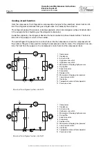
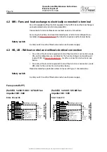
The safety circuit consists of a high pressure switch (HP), which protects by trip-
ping when there is high pressure in the system. Use the manual reset button on
the pressure switch to perform a reset.
For size 16-21
The safety circuit consists of a low pressure control and a high pressure switch
with a manual reset button. The safety circuit can trip for two different faults:
• High pressure in the system, HP (manual reset on the pressure switch)
• Low pressure in the system, LP (resets itself automatically)
Cooling function
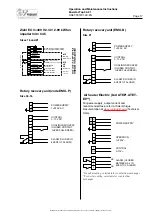
For integrated control equipment (MX), the cooling unit is interlocked across
the ventilation unit. If any of the fans stop, the cooling unit will also stop. The
interlock and demand signal is sent via Modbus.
For external control equipment (US, UC, MK), the interlock signal must be sent
via a potential-free relay. The demand signal must be sent via 0–10 V.
The cooling unit has internal communication between the frequency inverter and
the expansion valve’s control equipment. Communication takes place through
the Modbus protocol.
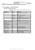
Circuit board
The circuit board in the cooling unit is internally prewired and tested at the fac-
tory.
The circuit board contains:
Size 04:
Control centre with integrated expansion valve controller
Size 06-12:
• Compressor inverter
• Expansion valve controller
• Contactor
Size 16-21:
• Main switch
• Fuse
• Control unit
• Control unit for expansion valve


