Page 44
Operation and Maintenance Instructions
Envistar Top 04-21
DSET.181201.00.EN
Continuous product development may give rise to specification changes without notice.
Fan size 04-06
Inspection
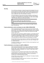
1. Remove one end of the fan assembly’s earth braid. If necessary, split the
motor cable's quick connector. Remove the screws (position 2) in the con-
nection plate (position 1) and unhook the fan unit from the key holes in the
anti-vibration supports (position 4), both upper and lower.
2. Check that the fan impeller with motor (position 5) rotates easily, is in bal-
ance and does not vibrate. Also check that the fan impeller is clean from any
accumulation of particles. Imbalance may be due to a coating or damage to
the fan impeller blades.
3. Listen to the sound from the motor bearings. If the bearings are in good
condition, you will hear a slight purring sound. A scraping or pounding sound
may mean that the bearings are damaged and service is then required.
4. Check that the fan impeller with motor (position 5) is firmly mounted in the
upper fan support (position 7) and that it has not shifted sideways toward the
inlet cone (position 6). Also check to make sure that the inlet cone is properly
secured.
5. The fan unit is mounted on the connection plate by means of rubber anti-vi-
bration mountings (position 3) between the lower fan support (position 8) and
the anti-vibration supports (position 4). Check that the anti-vibration mount-
ings are intact and are firmly fitted.
6. Check that the gasket on the connection plate (position 1) around the con-
nection opening is intact and is firmly fitted.
7. Check that the measurement tubes are securely fitted on each measurement
outlet.
8. Check that the edge protection on the upper fan support (position 7) is firmly
mounted and protects the cables that are wired to the junction box (position
9).
9. Reinstall the fan unit by hooking in on the key holes in the anti-vibration sup-
ports (position 4), both upper and lower, and secure the screws (position 2) in
the connection plate (position 1).
2
2
6
8
7
9
5
4
3
1
Fan unit
1. Connection plate
2. Screws (suspension)
3. Anti-vibration mounting
4. Anti-vibration support
5. Fan impeller with motor
6. Inlet cone
7. Fan support, upper
8. Fan support, lower
9. Junction box


