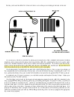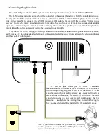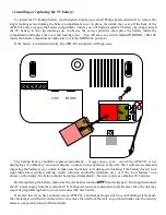
Before you mount the APD-T01 to the wall, turn it over so that you are looking at the back of the unit:
ANTI-TAMPER SWITCH
LINE
PHONE
TAMP TR2 TR1 0V 12V+
SPEAKER
BACKUP BATTERY
COMPARTMENT SCREW
TERMINAL BLOCK
PHONE JACKS
As you can see, the device provides two phone-jack connections so that a standard wall-mount or desktop
telephone can be connected to the phone line along with the APD-T01, permitting that line to be used to make
and receive standard telephone calls as well as alarm calls from the autodialer. If you don’t need this feature,
simply connect the telephone line to the LINE jack and leave the PHONE jack unconnected. Be sure not to mix
these two connections up, or the APD-T01 will not be able to dial out properly.
The backup-battery compartment is secured with a small Philips-head screw. There is also a raised ridge on
the compartment door to provide some friction-lock, so be careful when removing or replacing the cover. For
now, go ahead and remove the cover, and set both it and the screw aside, but do not install the 9V battery just yet.
In addition to the 9V battery connector, you will find a small switch marked “Normal / Erase.” Make sure
this switch is in the “Normal” position.
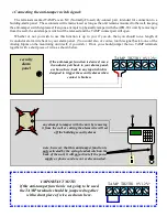
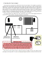
The first thing to do is hook up the trigger and anti-tampering signals from the APD-T01 autodialer to the
relay-equipped ITWatchDogs monitoring unit (and your building-alarm panel, if needed). For this, you will need
at least one length of 2-conductor wire – while we recommend using 2-conductor alarm-panel wire such as
Coleman Cable part# 511014501, Belden Wire & Cable part# 82442 8771000, or equivalent, any plain old 22
AWG copper wiring will suffice. Examples of these connections will be shown on the following pages. (For
purposes of illustration, these examples will assume the use of a RelayGoose-II monitoring unit; however, the
APD-T01 autodialer can be used with any ITWatchDogs monitoring unit or accessory equipped with appropriate
dry-contact relay outputs.)


