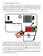
LINE
PHONE
TAMP TR2 TR1 0V 12V+
Connecting the AC power adapter:
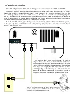
The last item to be connected to the APD-T01 unit is the AC power adapter. The autodialer is powered by a
standard 12VDC wall transformer-style power supply, similar to the one shown here, which is included with the
APD-T01 kit. Note that while the standard AC power adapter included with the kit has a U.S.-style plug for
120VAC/60Hz operation, it is actually capable of worldwide voltage (100 ~ 240VAC) and line-frequency (50 /
60Hz) operation. It is also compatible with power strips which provide 208VAC via IEC C-13 sockets connected
across two phases of a 3-phase power system, which are becoming increasingly common in larger IT installations;
all that is required is the appropriate plug-and-socket adapter. Power supplies with non-U.S. plugs may also be
available as an option; check with ITWatchDogs’ sales department for more details.
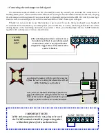
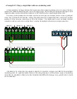
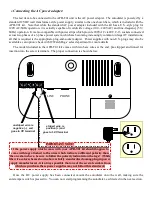
The model included in the APD-T01 kit comes with two bare wires at the end, pre-stripped and tinned for
insertion into the screw terminals. The proper connection is shown below:
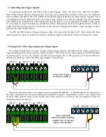
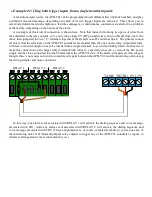
unstriped wire is
negative (–) and
goes to
0V
terminal
striped wire is
positive (+) and
goes to
12V
terminal
IMPORTANT NOTE!
If the power supply which comes with your APD-T01 kit should happen to
come with tags attached to the wires which indicate a different polarity than
the one shown here, be sure to follow the polarity indicated on the tags! (While
the wire-color scheme shown above is fairly standardized among plug-in power
supply manufacturers, it is always possible that one of the several vendors from
which we purchase these power supplies may not follow this standard.)
Once the DC power supply has been connected, mount the autodialer onto the wall, making sure the
anti-tamper switch is pressed in. You can now start programming the autodialer, as directed in the next section.


