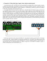
As mentioned previously, the APD-T01 can be programmed to call different lists of phone numbers, and play
a different recorded message, depending on which of its two trigger inputs are activated. This allows you to
selectively determine which employees, facilities managers, or maintenance contractors are alerted to a problem
at the facility, depending on the nature of the alarm.
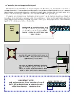
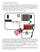
An example of this kind of connection is shown here. Note that instead of running two pairs of wires from
the autodialer to the relay outputs, we’ve only run a single 0V (DC ground) wire (shown in black) from one to the
other, then jumpered the two “C” terminals together at the RelayGoose-II’s terminal block. The primary reason
for this is that the terminals on the APD-T01 autodialer are smaller than the ones on the relay output terminals,
with less room for multiple wires to be inserted into a single terminal, so you will probably find it much easier to
make this connection on the larger relay terminal block instead – especially since the (–) side of the DC power
supply also has to be connected into the 0V terminal at the APD-T01 side. If the alarm-wire pairs are thin enough,
though, there’s no reason not run two complete wire pairs between the APD-T01 and the monitoring unit to keep
the wiring simpler and more consistent.
NC
NO
C
NC
NO
C
NC
NO
C
RELAY 1
RELAY 2
RELAY 3
In this way, any alarm event associated with RELAY 1 will activate the dialing sequence and voice message
associated with TR1, while any alarm event associated with RELAY 2 will activate the dialing sequence and
voice message associated with TR2. (These assignments are, of course, completely arbitrary; you can use any of
the monitoring unit’s NO (Normally Open) relay outputs to trigger any of the APD-T01 autodialer’s inputs, in
whatever arrangement is most convenient to you.)
Example #2: Using both trigger inputs from a single monitoring unit:
TAMP TR2 TR1 0V 12V+


