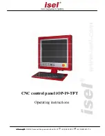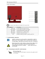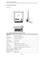
CNC control panel iOP-19-TFT
Page - 12
3.3 Machine control element connection
Pin assignment for the D-sub 25-pin plug
Pin Signal
Labeling
1
EMERGENCY
STOP_1
EMERGENCY Stop Channel 1, Connection 1.1
2
EMERGENCY
STOP_1
EMERGENCY Stop Channel 1, Connection 1.2
3
EMERGENCY
STOP_2
EMERGENCY Stop Channel 2, Connection 2.1
4
EMERGENCY
STOP_2
EMERGENCY Stop Channel 2, Connection 2.2
5
24V
+24V DC
6
POWER BTN
Power button input
7
POWER LAMP
Power lamp output
8
24V
+24V DC
9
KEY SWITCH Test
Key switch input test mode
10
KEY SWITCH Auto
Key switch input automatic operating mode
11
24V
+24V DC
12
ACK_1
Channel 1 enabling switch input
13
24V
+24V DC
14
ACK_2
Channel 2 enabling switch input
15
COVER SWITCH
Cover switch input
16
COVER SWITCH
Cover switch output
17
GND
18
19
20
FAULT LAMP
Control panel fault lamp output
21
START BTN
Start button (closing contact)
22
STOP BTN
Stop button input (opening contact)
23
START LAMP
Start lamp output
24
STOP LAMP
Stop lamp output
25
not available
D-sub 25-pin plug control element
This cable allows the control elements (buttons and switches) on the front
cover of the CNC control panel to be connected to the corresponding
safety circuit modules in the switching cabinet.
Power (+24V DC) to the USB hub on the control panel is provided by
this cable.
Make sure that the keyboard, touch screen and USB interfaces only
function when connected to the safety circuit modules.

