background image

3) Click on the 

[

 Start 

]

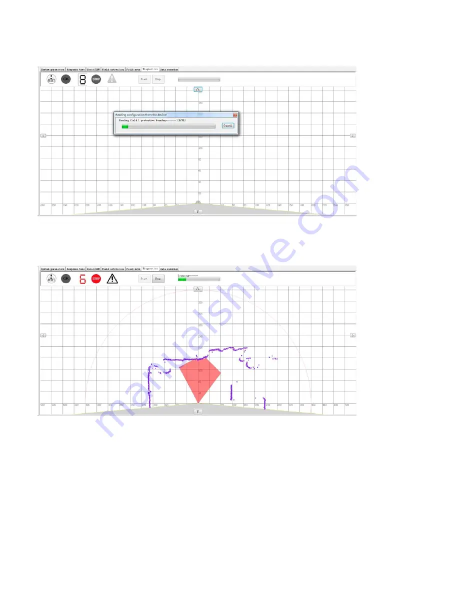
 icon to read the configuration information from the LSPD scanner, a pop-up window 

will appear and display the process as shown in Fig.3.3.2.

Fig.3.3.2 Reading configuration information 

4)  When the configuration information reading is finished, the corresponding protective area will be displayed,
the indicator window status, and the scanner will update in real time, as shown in Fig.3.3.3. 

Fig.3.3.3 Boundary data and surrounding outline data 

5)  I this way the user can determine the exact location of the obstacle by comparing the boundary outline of 
the protective field and the surrounding outline.

Tip:

 The method of reading the device configuration (see Chapter 

3.6

) + Scan the minimum outline (see 

Chapter 

3.2.2.2.2

) in Filed sets tab, also can display the boundary outline of the protective field and the 

surrounding outline. This method can locate the obstacle easily.

6)   To halt the real-time scan click the 

[

 Stop 

]

 icon this will stop the diagnosis function and the surrounding 

outline information is no longer be updated. To restart the diagnostics simply click on the 

[

 Start 

]

 icon again. 

53

Содержание LSPD

Страница 1: ...LSPD Safety Laser Scanner Configuration Software Manual ISB 167811 Canada Inc 2300 rue Victoria Lachine Canada H8S 1Z3 July 2016 1 ...

Страница 2: ...guide the configuration and diagnosis of LSPD This operation manual mainly introduces installation removal user interface application examples frequent questions and solutions of LSPD configuration software The LSPD configuration software is not applicable for products of other brands with similar function For damages or losses caused by improper use of the configuration software the company assum...

Страница 3: ...m 20 2 5 Setting area 21 2 5 1 System description 21 2 5 2 Scan times Response time setting 21 2 5 3 Reset EDM setting 22 2 5 4 Field activation 22 2 5 5 Field sets 24 2 5 5 1 Field selecting small view 24 2 5 5 2 Area editing toolbar 25 2 5 5 2 1 Toolbar commands introduction 25 2 5 5 2 2 Free drawing tool 27 2 5 5 2 3 Straight line tool 28 2 5 5 2 4 Sector tool 29 2 5 5 2 5 Rectangle tool 30 2 5...

Страница 4: ...ive field configuration 51 3 2 5 1 Switch to Field sets 51 3 2 5 2 Field 1 configuration 51 3 2 5 3 Field 2 configuration 51 3 2 6 Transfer configuration to scanner 52 3 3 Diagnostics example 52 3 4 Window diagnostics example 54 3 4 1 Window dirty diagnosis 54 3 4 2 Window calibration 55 3 5 Example of transferring configuration information to another LSPD 55 3 6 Transfer configuration to scanner ...

Страница 5: ...e computer the NET Framework 4 0 will be installed automatically when LSPD software is installed 1 2 Software installation and uninstallation 1 Installation of LSPD configuration software Start windows and put the disk into CD ROM Find file LSPD configuration software installation package and double click the setup exe Follow the instruction to complete the installation If the installation is prev...

Страница 6: ...6 ...

Страница 7: ...wn in Fig 2 1 1 Fig 2 1 1 Configuration preparations 2 1 2 USB driver installation Only the first connection requires driver installation Connect the computer to the LSPD scanner using the configuration cable Windows 7 or above operating system will identify LSPD and install the driver automatically For Windows XP system a dialog box will be popped up to prompt that new hardware wizard has been fo...

Страница 8: ...time only click Next as shown in Fig 2 1 2 1 Fig 2 1 2 1 Find new hardware wizard 2 Select Install from a list or specified location Advanced and click Next as shown in Fig 2 1 2 2 Fig 2 1 2 2 Find new hardware wizard 8 ...

Страница 9: ...oose the driver to install and click Next as shown in Fig 2 1 2 3 Fig 2 1 2 3 Driver installation wizard 4 Select USB Serial Port in the device model list and click Next as shown in Fig 2 1 2 4 Fig 2 1 2 4 Selecting USB Serial Port 9 ...

Страница 10: ...hat driver is being installed as shown in Fig 2 1 2 5 Fig 2 1 2 5 USB driver installation 6 The following window will pop up after installation Click Finish to finish the installation as shown in Fig 2 1 2 6 Fig 2 1 2 6 Finish new hardware wizard 10 ...

Страница 11: ...ation once according to the previous steps and the USB driver installation will be finished 8 After the USB driver properly installed users can view the COM port between the scanner and the computer the specific steps are as follows Right click My Computer and click Manage menu item in the pop up menu as shown in Fig 2 1 2 8 Fig 2 1 2 8 Right click My Computer 11 ...

Страница 12: ...opup window as shown in Fig 2 1 2 9 Fig 2 1 2 9 Device manager Expand the Ports COM LPT branch of Fig 2 1 9 of which the USB Serial Port COM is the COM port connected to LSPD as shown in Fig 2 1 2 10 Fig 2 1 2 10 USB serial port 12 ...

Страница 13: ...s than 2 that means the scanner is not recognized refer to Chapter 4 to solve this problem Fig 2 1 5 1 Serial port selection window Click Ok if the pop up box prompts the connection is successful as shown in Fig 2 1 5 2 then the scanner has been connected to the computer successfully and the Nixie tube of the indicator window displays 6 Fig 2 1 5 2 Connection successful Click Ok or close the pop u...

Страница 14: ... can also be started by double clicking the shortcut icon The user will see the following interface after the software has started as shown in Fig 2 1 6 1 Fig 2 1 6 1 Software start interface 2 1 6 1 Exit the LSPD configuration software To exit the program please click the red close button X at top right corner of the interface Or you can exit from the main menu tabs by clicking on File and select...

Страница 15: ... Menu Device information bar Toolbar Tree diagram Project editing zone and Status bar as shown in Fig 2 2 1 Fig 2 2 1 Program user interface 2 2 1 Menu Menu structure of user interface consists five sub menu 1 File 2 Device 3 Extras 4 View 5 Help as shown in Fig 2 2 1 1 Fig 2 2 1 1 Menu view 15 1 2 3 4 5 Tree diagram Toolbar Menu Device information Status bar Project editing zone ...

Страница 16: ...per software version and website 16 Save the current project Save the current project with a different name Create a new project Open a project file Quit the application Preview for the current project Transfer the current configuration to the device Detecting the protective cover status and calibrating the cover after replacement Reading configuration from the connected device Change the user gro...

Страница 17: ...mation bar 3 Show or hide tree diagram Show or hide tree diagram 4 Show or hide status bar Show or hide status bar 5 Input area setting Transfer area configuration information saved as xml file in the computer to configuration software 6 Output area setting Transfer area configuration information set in configuration software to the computer and save it as xml file 7 Transfer configuration to devi...

Страница 18: ...ice configuration operation for project file check window check etc Limited function Transfer configuration to device Administrator access Password is required All functions are available Administrator log in steps are as following 1 Click tool bar icon Change user group or Click menu bar Extra Change user group to open Change user group as shown in Fig 2 3 1 2 Fig 2 3 1 2 Change user group 2 To c...

Страница 19: ... administrator log in The administrator can change password after log in Click menu bar Extras Change administrator password the pop up window is shown in Fig 2 3 1 6 Enter the old password and new password enter the new password a second time to confirm and click Ok to finish the change Fig 2 3 1 6 Change administrator password 19 ...

Страница 20: ... is shown in Fig 2 4 1 Fig 2 4 1 Tree diagram For example when you click on Field activation in the tree diagram the corresponding Field activation tab will be highlighted displayed in set area as shown in Fig 2 4 2 This is convenient for user to check and change configuration parameters Fig 2 4 2 Tree diagram and setting area tab 20 ...

Страница 21: ...recorder as shown in Fig 2 5 1 Fig 2 5 1 Setting area 2 5 1 System description System parameters tab is used to set application name device name and user name as shown in Fig 2 5 1 2 5 2 Scan times Response time setting Fig 2 5 2 1 Response time tab Response time tab is used to set scan times of LSPD the setting range is 2 to16 times and the corresponding response time range is 80 to 640ms as show...

Страница 22: ...afety Laser Scanner Operation Manual A field consists of one protective field protective area and one warning field warning area Fig 2 5 4 1 Field activation tab Setting areas includes the selection of four fields and definition of the external input signal Z1 Z2 Z3 and Z4 LSPD can configure four fields at most Each field consists of a protective field maximum radius of 4 meters and a warning fiel...

Страница 23: ...re four field selecting small views Users must check in the Field activation tab and activate it then the field can be edited in the Field sets tab According to the following settings Field 1 and Field 2 are activated Field 3 and Field 4 are disabled When Z1 is a high level input Z2 is a low level input Z3 is a high level input Z4 is a low level input Field 1 is activated When Z1 is a low level in...

Страница 24: ...ecting small view Choose the field whose boundary will be edited When a field is selected the corresponding small view displays blue frame as shown in Fig 2 5 5 1 1 field 2 has been selected its protective field and warning field can be edited Fig 2 5 5 1 1 Field 2 small view and delete button To delete the drawing area Click the delete button X in top right corner of the view 24 1 4 2 3 ...

Страница 25: ... selected 3 Warning field Warning field can be edited after it is selected 4 Area switchover Switch protective field and warning field 5 Select Select one or a range of boundary points in the current drawing area 6 Undo Withdraw the last step operation can continuous withdraw 7 Redo Regain the last step operation can continuous regain 8 Copy Copy the current selected boundary points 9 Paste Paste ...

Страница 26: ...e user defined point Display the user defined point after it is clicked 21 Conceal all points Do not display any boundary point after it is clicked 22 Set Users can rotate the canvas according to the actual scanning area see details below 23 Point editing Modify the boundary points of the current editing area after it is clicked see details below 24 Scan the minimum outline Scan the minimum outlin...

Страница 27: ...e click mouse once at coordinates X 0 Y 200 in the drawing area it will generate a boundary point as shown in Fig 2 5 5 2 2 1 below Fig 2 5 5 2 2 1 Draw a single boundary point Or press the left button of mouse and drag to generate a range of boundary Fig 2 5 5 2 2 2 Draw a range of boundary points 27 Draw a range of points ...

Страница 28: ...mouse once at coordinates X 0 Y 200 in the drawing area to set the starting point of the straight line then click the left button of mouse once at coordinates X 100 Y 100 to set the ending point of the straight line the corresponding protective field generated is as shown in Fig 2 5 5 2 3 1 Fig 2 5 5 2 3 1 Draw a straight line 28 Endpoint Starting point ...

Страница 29: ...n of mouse at coordinates X 0 Y 200 in the drawing area to set the starting sector angle 90 then drag the mouse to coordinates 160 120 to set the sector radius 200cm and ending angle 143 28 Release the left button the corresponding protective field generated is as shown in Fig 2 5 5 2 4 1 Fig 2 5 5 2 4 1 Draw a sector 29 ...

Страница 30: ...in Fig 2 5 5 2 5 1 below Fig 2 5 5 2 5 1 Rectangle settings Input length and width of the rectangle according to the user s demand as shown in Fig 2 5 5 2 5 1 length is set to 200 left length and right length is set to 50 and click OK the protective field is generated as shown in Fig 2 5 5 2 5 2 Fig 2 5 5 2 5 2 Draw a rectangle 30 ...

Страница 31: ...2 5 5 2 6 1 Fig 2 5 5 2 6 1 Settings command sub window Users can rotate the canvas according to the actual scanning area For example select Bottom and click Ok the canvas in drawing area as shown in Fig 2 5 5 2 5 2 will be rotated as shown in Fig 2 5 5 2 6 2 Fig 2 5 5 2 6 2 Rotating the canvas 31 ...

Страница 32: ... by the list form Coordinate input Modifying user defined coordinates data of boundary points Provide XY coordinate input and polar coordinates input Operation Example Suppose you have defined the protective field as shown in Fig 2 5 5 2 5 2 rectangle the functions of Modify Add and Delete will be introduced 1 Change boundary points of the rectangular area as shown in Fig 2 5 5 2 5 2 Click and sel...

Страница 33: ... Protective field after coordinates have been modified 2 Add boundary points to protective field shown in Fig 2 5 5 2 7 3 Click the XY coordinate icon in the toolbar than click enter the coordinates into the field edit pop up menu For example Input XY coordinates 100 100 or polar coordinate data in the XY input as shown in Fig 2 5 5 2 7 4 33 ...

Страница 34: ...data Click Save to save the user defined boundary points 100 100 has been added in Fig 2 5 5 2 7 5 Fig 2 5 5 2 7 5 Add boundary points Click Quit to close the pop up window the modified protective field will be as shown in Fig 2 5 5 2 7 6 34 ...

Страница 35: ... boundary points of protective field shown in Fig 2 5 5 2 7 6 Click and select coordinates 50 50 which will be deleted in the boundary points list view at the left part of the pop up window as shown in Fig 2 5 5 2 7 7 Fig 2 5 5 2 7 7 Selecting boundary points to be deleted 35 ...

Страница 36: ...t view disappears as shown in Fig 2 5 5 2 7 8 Fig 2 5 5 2 7 8 Delete the selected boundary points Close the pop up window the modified protective field will be as shown in Fig 2 5 5 2 7 9 Fig 2 5 5 2 7 9 Protective field after coordinates have been deleted 36 ...

Страница 37: ...l The origin of the canvas corresponds to the center of the LSPD where the scanner located Canvas can be moved by four directional buttons or dragged by clicking on the toolbar icon The gray part of coordinate area can not be edited Different editing areas correspond to different colors as shown in Sheet 4 and Fig 2 5 5 3 1 Sheet 4 Color allocation of editing area Outline Color Current editing pro...

Страница 38: ...er can select the Diagnostics tab to monitor the scanner in real time displaying status of the indicator window on the scanner the outline of current field and the outline of the surrounding as shown in Fig 2 5 6 1 Fig 2 5 6 1 Diagnostics tab Canvas area Showing the boundary outline surrounding outline of the current protective field Start button This will activate diagnosis function after the con...

Страница 39: ...ed to work Warning The light is on when object detected in warning field ALARM output ON Nixie tube 0 Protective warning field not set or the field input signal fault 1 Current scanning area is protective warning field 1 2 Current scanning area is protective warning field 2 3 Current scanning area is protective warning field 3 4 Current scanning area is protective warning field 4 5 OSSD output fau...

Страница 40: ... when diagnostics are being carried out as shown in Fig 2 5 7 1 Fig 2 5 7 1 Data recorder tab 2 6 Status bar The Status bar will display the connection status and the current user as shown in Fig 2 6 1 Fig 2 6 1 Status bar Offline Software and scanner are not connected User Operator The default log in is operator after the software has been opened 40 ...

Страница 41: ... Finish the configuration preparations as described earlier in chapter 3 1 USB driver only needs to be installed for the first connection the scanner can be identified automatically after 3 1 2 Guard field configuration 3 1 2 1 Switch to Field sets Switch to the corresponding drawing area through the tree diagram or Field sets tab as shown in Fig 3 1 2 1 Fig 3 1 2 1 Drawing area 3 1 2 2 Guarding f...

Страница 42: ...regular boundary Fig 3 1 2 2 1 1 Draw protective field Step 2 Warning field configuration Click the icon or to switch to warning field configuration finishing boundary configuration As an example Fig 3 1 2 2 1 2 shows the user defined protective field in red and the warning field in yellow with an irregular boundary Fig 3 1 2 2 1 3 shows the user defined warning field with the irregular boundary F...

Страница 43: ... to obtain a real time scan of the surrounding area as shown in Fig 3 1 2 2 2 1 Fig 3 1 2 2 2 2 Test piece location Step 2 Click on the tab Stop scanning outline in the toolbar to halt the real time scan Now you can create the protective area and warning area by using the drawing tool as shown in Fig 3 1 2 2 2 3 Fig 3 1 2 2 2 3 Draw protective field referring to test piece location 43 ...

Страница 44: ...ective area configuration is as shown in Fig 3 1 2 2 2 4 Fig 3 1 2 2 2 4 Draw protective field referring to outline Step 4 Warning field configuration Click on the icon or to switch to thewarning field configuration Repeat the above steps to finish the warning field configuration 44 ...

Страница 45: ...ote Ensure that the test piece is the nearest object from the scanner when it is moving around the boundary Step 2 Click on the tab Stop scanning the minimum outline and the protective field boundary will no longer be updated in real time The user can modify the boundary according to the actual needs For example suppose user needs the protective field of 45 to 135 The user will use the drawing too...

Страница 46: ...onfiguration file can be saved on the computer by clicking on the icon in the toolbar The configuration file is saved as a xml file Or as a bin project file 3 1 2 2 5 Importing a saved guarding field Step 1 To import a previously saved file the user will click on the icon in the toolbar and open a saved xml configuration file as shown in Fig 3 1 2 2 5 1 Fig 3 1 2 2 5 1 Import area configuration fi...

Страница 47: ...transfer the configuration to the scanner The user needs to switch the user group to administrator to finish the configuration transfer Specific steps are as follows Click on the icon in the toolbar to open the user group menu as shown in Fig 3 1 3 1 Change the User group to the administrator enter the log in password the default password is 123123 click log in Fig 3 1 3 1 User group switching Aft...

Страница 48: ...will disappear and the Nixie tube on the LSPD scanner will display 9 Reminder After the user has completed the configuration it is recommend that the file be saved as a bin To save the file click on the File tab Save as then select project bin The user may change the name as required After successful configuration click on the icon to disconnect the pop up window will prompt that disconnection is ...

Страница 49: ...blish connection between scanner and software Finish the configuration preparations as described earlier in chapter 3 1 USB driver only needs to be installed for the first connection the scanner can be identified automatically after 3 2 2 Set Response time Switch to the corresponding setting area through the tree diagram or Response time tab set Scan times to 4 and Response time to 160ms as shown ...

Страница 50: ... of Z1 Z2 Z3 and Z4 has now changed to the selectable as shown in Fig 3 2 4 2 Fig 3 2 4 2 Field activation selecting Step 3 Set different combination of the external input signal for Field 1 and Field 2 As shown in Fig 3 2 4 3 when Z1 is input high Z2 is input low Z3 is input high Z4 is input low Field 1 is activated when Z1is input low Z2 is input high Z3 is input high Z4 is input low Field 2 is ...

Страница 51: ...undary editing area 3 2 5 2 Field 1 configuration Refer Chapter 3 2 2 2 for the method to set the protective field protective field and warning field of Field 1 3 2 5 3 Field 2 configuration Step 1 Click the corresponding Field selecting small view the second one from the top down and the small view of Field 2 will show blue border after it is selected as shown in Fig 3 2 5 3 1 Fig 3 2 5 3 1 Activ...

Страница 52: ...le click on the File tab Save as then select project bin The user may change the name as required 3 3 Diagnostics example Diagnosis function is used provide a real time scan of the prtective area to solve a problem when the obstacle intruded into the protective can not be located accurately Specific operation methods are as follows 1 Finish configuration preparations according to Chapter 3 1 2 Swi...

Страница 53: ...line data 5 I this way the user can determine the exact location of the obstacle by comparing the boundary outline of the protective field and the surrounding outline Tip The method of reading the device configuration see Chapter 3 6 Scan the minimum outline see Chapter 3 2 2 2 2 in Filed sets tab also can display the boundary outline of the protective field and the surrounding outline This method...

Страница 54: ...fic operation methods are as follows 1 Connect a computer and verify the connection as described in Chapter 3 1 2 In the main menu area click on Device then select Protective cover diagnostics Pop up window is shown in Fig 3 4 1 1 Fig 3 4 1 1 The diagnosis and calibration of the window In Fig 3 4 1 1 the blue column diagram represents the reference signal amplitude of the window and orange column ...

Страница 55: ...on information to another LSPD The user can read configuration information from one scanner save it and transfer it to another scanner In certain installations the user may want to transfer the configuration information from scanner A to scanner B specific steps are as follows 1 Establish connection between a computer and scanner A and finish configuration preparations according to Chapter 3 1 2 I...

Страница 56: ... 0 during the transmission As shown in Fig 3 6 1 Fig 3 6 1 Transfer configuration to scanner When the transfer is complete the pop up window will disappear and the Nixie tube on the LSPD scanner will display 9 Reminder After the user has completed the configuration it is recommend that the file be saved as a bin To save the file click on the File tab Save as then select project bin The user may ch...

Страница 57: ...e COM port connections and port number Note To view the COM port which the scanner corresponds to refer to step 8 in Chapter 3 1 2 3 If the scanner s USB Serial Port COM can be found but does not respond to a connection it is recommended to uninstall and reinstall the USB driver Refer to the method described in Chapter 4 1 1 6 Carry out configuration preparations again according to Chapter 3 1 and...

Страница 58: ...n Fig 4 1 1 2 Fig 4 1 1 2 USB Serial Port uninstall confirm 4 Right click at the Device Manager Universal Serial Bus Controllers USB Serial Converter and select Uninstall as shown in Fig 4 1 1 3 Fig 4 1 1 3 USB Serial Converter uninstall 58 ...

Страница 59: ...install methods 4 3 Other problems In the case of software errors and problems in programming it is recommended that the user close the configuration software disconnect the computer from the LSPD scanner reboot the computer and power cycle the LSPD scanner After the computer and scanner have restarted reconnect the computer to the scanner and start the program If you encounter other abnormal phen...

Отзывы: