


iDS6
Series User’s Manual
iS5 Communications Inc.
28
5.1.3.5
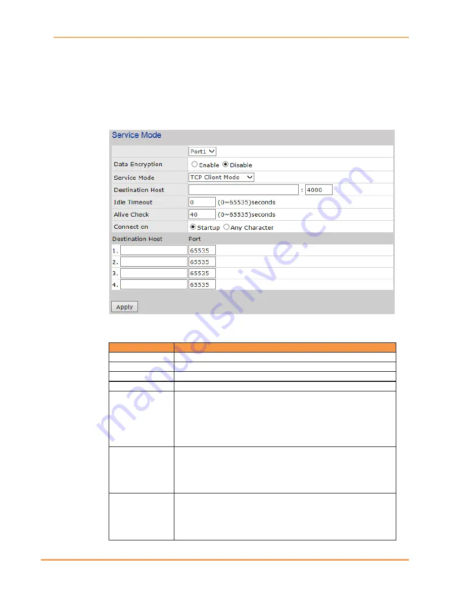
Service Mode – TCP Client
In TCP Client Mode, the Device Server can establish a TCP connection with a server by
the method you set (Startup or any character). After the data has been transferred, the
Device Server can disconnect automatically from the server by using the TCP Alive Check
time or Idle Timeout settings.
Service Mode – TCP Client interface
The following table describes the Service Mode – TCP Client interface page.
Label
Description
Port
Select a port (1-4) to see the settings.
Data Encryption
Can be enabled or disabled. SSL data encryption is used.
Service Mode
Select TCP Client Mode. The default is Virtual COM Mode.
Destination Host
Set the IP address of host and the port number of the data port.
Idle Timeout
When the serial port stops data transmission for a defined period of
time (Idle Timeout between 0 and 65535 seconds), the connection
will be closed and the port will be available to connect with other
hosts. When set to 0 this function is disabled. The factory default
value is 0. If Multilink is configured, only the first host connection is
effective for this setting.
Alive Check
The serial device will send TCP alive-check packet in each Alive Check
defined time interval (0 to 65535 seconds) to the remote host to
check the TCP connection. If the TCP connection is not alive, the
connection will be closed and the port will become available. When
set to 0 this function is disabled. The factory default value is 40.
Connect On
Select when the Device Server will connect. Select between:
Startup
: the TCP Client will make a TCP connection once the
connected serial device is started.
Any Character
: the TCP Client will make a TCP connection once the
connected serial device starts to send data.


