FLAIL MOWER - FM Series
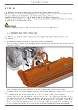
• finally adjust the parking stand, placing it at the highest point by means of the related elastic pin.
WARNING
Before connect the flail mower to the tractor, make sure that tractor and flail mower are on a flat, stable and
dry surface
4.2. DRIVELINE INSTALLATION
The gearbox unit is equipped with a free wheel inside, able to absorbe the rotor inertia during stop- ping,
and to prevent possible damage to the transmission system machine-tractor that would be caused by an
instantaneous stop of the rotor.
Consequently, the use of a cardan shaft with free wheel is not required.
Before installing the driveshaft, the operator must read the manuals of driveshaft and tractor, checking in
particular that rpm and direction of rotation of the tractor PTO match those of the flail mower.
If the direction of rotation of the PTO tractor does not match that of the machine, contact the Manufacturer
or your Dealer.
To connect the driveshaft to the tractor and implement, the operator must:
•
park tractor and flail mower on a flat surface, with parking brake set, engine off, and ignition key
removed;
•
check that driveshaft, flail mower and tractor are in good condition, otherwise provide for their
replacement;
•
remove the PTO shield of the flail mower through the fixing screws;
•
insert the driveline yoke on the implement PTO by first lining up the splines, then ensure its tightening
onto the shaft through its fastener/snap pin;
•
replace the PTO shield of the flail mower through the fixing screws;
•
insert the driveshaft yoke on the tractor PTO, then ensure its tightening onto shaft through its fastener;
•
hook to the tractor and flail mower the two retaining chains of the driveline shielding, to prevent
shielding rotation during functioning of the machine.
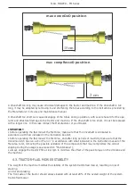
DRIVELINE LENGTH CHECK
Before operating the flail mower, ensure that the size of driveshaft is adequate. The driveshaft
supplied with the machine has a standard length, therefore it may need an adaptation of the
length, depending of the tractor which the flail mower is combined.
The length of the driveshaft must be such to:
• avoid bottom out of the transmission tubes, when the driveshaft is in compressed position (when flail
mower is raised up off the ground);
• ensure an overlapping of the transmission tubes enough to transmit the torque required, when the
driveshaft is in max extension (when flail mower is in its lowest position in the ground).
When the driveshaft is at its minimum length (max compressed position), there must be at least a
2 cm of distance between the ends of each transmission tube and the yokes side.
When the driveshaft is at its maximum operational extension, there must be an overlap between
the tubes profiles of 15 cm at least.
Содержание FMH Series
Страница 16: ...FLAIL MOWER FMH Series 17 F SAFETY LABELS POSITION AND DESCRIPTION 2 1 5 4 12 8 9 7 6 13 11 3 3 ...
Страница 43: ......
Страница 45: ......
Страница 46: ...FLAIL MOWER FMH Series NOTES ...
Страница 47: ...FLAIL MOWER FMH Series NOTES ...


