Assembly Instructions
Tool Changer TK-35
WZW_TK-35_V2.0
3
1
2
3
7
5
9
10
6
8
4
11
2.6.
17B
Requirements placed on the personnel
The variety of tasks described in these instructions place differing
requirements on the qualifications of those performing these
tasks.
Only appropriate specialist personnel or a duly instructed person
under the supervision of specialist personnel are allowed to carry
out any work such as assembly, commissioning, operating,
dismantling and maintenance.
In view of his technical training, knowledge, experience and
knowledge of the relevant standards and regulations, the
specialist is in a position to perform the work he has been
entrusted with and - on his own - to recognize/avoid any hazards.
3.
2B
Specifications
(Please refer to the ongoing catalogue or the internet for
specifications of the individual tool changers.)
3.1.
18B
General basic data
Min. operating pressure:
4,5 bar
Max. operating pressure: 8 bar
Temperature range:
5 °C to 80 °C (higher if requested)
Drive:
Pneumatic with fail-safe spring
Material:
Casing of high-strength aluminium hardcoat-
ed/Operating parts hardened tool-steel
Tolerance particulars
Thread:
+/− 0.1 mm
Alignment pin drill hole:
+/− 0.02 mm
3.2.
19B
Operating conditions
The working environment is not to contain any dirt, dust, spray or
vapours. The machine is to be used at temperatures between
10 °C and 40 °C.
The maximum (non-condensing) relative air humidity is to be
between 10% and 70%.
4.
3B
Setup and function
4.1.
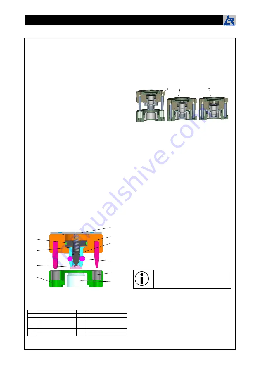
20B
Overview
1
Cover
8
Closing cover
2
Robot Side
9
Tool Side
3
Ball Bushing
10
Centering Bushing
4
Piston
11
Locking Bushing
5
Fail-Safe Spring
6
Taper Pin
7
Ball
4.2.
21B
Brief description
The locking mechanism of the tool changing system is realized
over balls. The balls are pressed over a bevel in a receptacle.
With air pressure loss the balls are held in the receptacle by a
spring integrated in the cylinder, whereby an automatic locking is
ensured with decrease of pressure. Contacts fitted with springs
are used for the signal transmission. Thanks to the springs a
bend of the contacts can be avoided. The individual contact pins
can be exchanged individually by a patch cord. Thereby a high
life span and transmission reliability are ensured.
Principle illustration: (1) System decoupled; (2) System coupled; (3)
System locked
Power and moment transmission is by means of two generously
proportioned pins that also function as an antitwist protector.
After the system is locked, the TK 35 tool changer system can
transfer 5 pneumatic lines and - with the aid of the plug connect-
ors - 15 electrical signals from the robot side to the tool side.
Tool changer of the TK-series provide a number of benefits:
For fast and problem-free changing from tools and grippers
at robots or gantries up to a payload of 1000kg.
Transmissionof electrical signals by spring fitted contact
pins
Coupling and uncoupling of pneumatic and hydraulic lines.
Specific splash-proof execution (optional)
IP 65 sealed electrical signal transmission (optional)
Tool changer with internal routing (optional)
Stainless steel tool changer (optional)
5.
4B
Transport, packing, storage
5.1.
22B
Transport
Immediately check on the delivery when received as to
completeness and any transportation damage.
Proceed as follows if there are signs of external damage:
Do not accept the delivery or only under reservation.
Note down the extent of damage on the transportation
documents or on the forwarder's delivery note.
Initiate the complaint procedure.
Object to any shortcoming as soon as it is
discovered. Claims for damages can only be filed
within the valid time spans as set aside for
complaints.
Transportation temperature −20 °C to 65 °C.
Protect against external impact (jolt, blow, vibration)


