IPG YLS-1000-K Скачать руководство пользователя страница 132

​ | Messages and troubleshooting

132

YLS-K

There are two ways to save the log files:

Save individual log files from a certain day via the  Load  button.

Save all log files over a certain time period via the  Zip All  button.

Load

4.

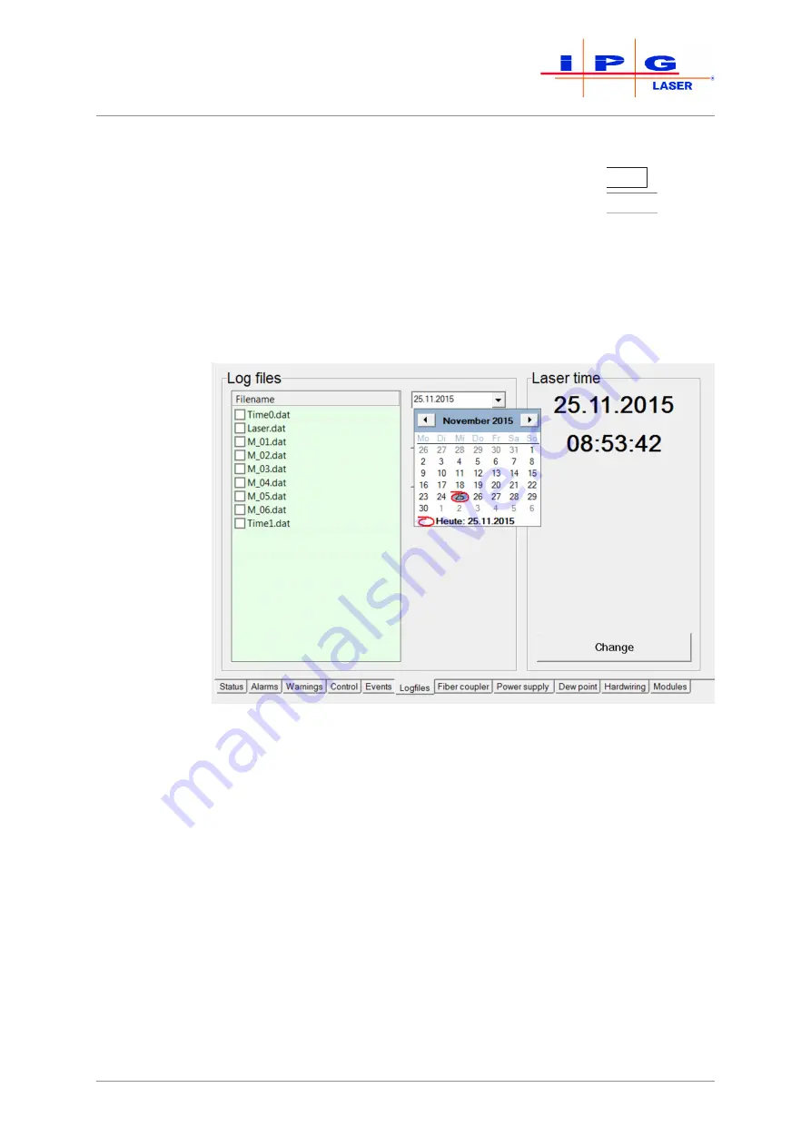
Select  the  date  on  which  the  fault  occurred.  If  the  date  is  not
known,  you  can  use  the 

Events

  tab  to  find  the  corresponding

date.

In  the  File  name  field,  a  list  appears  with  the  existing  log  files  from  the  selected
date. If on the selected date the laser was not switched on, no log files were gen-
erated for the date and the File name field remains empty.

Figure 79: 

Select date

5.

Using 

Configuration\LaserNet\Settings\Paths… 

se-

lect the folder in which you want to save the log files. The folder

C:\User\My  Documents\IPG  Laser  GmbH\

 is selected by

default.

Содержание YLS-1000-K

Страница 1: ...High Power Fiber Laser Series YLS K Output power 1 to 3kW Translation of the Original Operating Manual Installation Operation and Maintenance Document Number G21 550064 000 Date 25 10 2018...

Страница 2: ......

Страница 3: ...use 19 2 4 Obligations of the system owner 19 2 5 Responsibility of the operating personnel 20 2 6 Personnel qualifications 20 2 7 Safety conscious working 21 2 8 Personal protective gear 21 2 9 Speci...

Страница 4: ...he product 45 5 4 Running lines and fibers 45 5 5 Connecting the product 46 5 5 1 Connecting the supply voltage 47 5 5 2 Connecting the external interfaces 50 5 5 3 Connecting the fiber connector to t...

Страница 5: ...8 6 Logfiles tab 100 8 8 7 Power supply tab 101 8 8 8 Chiller tab 102 8 8 9 Dew point tab 104 8 8 10 Hardwiring tab 105 8 8 11 Modules tab 105 8 9 LaserNet program editor 106 8 9 1 LaserNet program e...

Страница 6: ...ng the firmware and product configuration 138 10 4 6 Resetting critical errors 139 11 Decommissioning and disposal 141 11 1 Temporary decommissioning 141 11 2 Permanent decommissioning 142 11 3 Dispos...

Страница 7: ...re to follow the safety instructions can lead to personal injuries dam age to the device or environmental damage This operating manual must be kept in the product s immediate vicinity and accessible t...

Страница 8: ...arantees that this product satisfies all applicable specifications in normal operation During the warranty period IPG Laser GmbH may choose to repair or replace a product that is found to be defective...

Страница 9: ...thereby voiding the war ranty Reservation of the right to make amendments IPG Laser GmbH reserves the right to make changes to the design or construction of its products at any time without any oblig...

Страница 10: ...ommissioning report Circuit diagram Layout of the installation panel Accessories list Technical data Declaration of Conformity Additional system documents in accordance with contractual agree ments 1...

Страница 11: ...The possible consequences of failure to heed the warning are for exam ple crushing injuries burns or other severe injuries Additional expla nations can also be given here Measures prohibitions Actions...

Страница 12: ...voided this could lead to light or moderate injuries NOTICE If this notice is not heeded there is a risk of damage to the product or other property damage Additional in structions Important notice Sho...

Страница 13: ...order 1 Action 1 2 Action 2 Individual instruction work instruc tion without specific order and de scription of result Action Condition result after perfor mance of the action or addi tional explanat...

Страница 14: ...L3 Phase conductor LAN Local area network LC Laser chiller LCA Laser connector automotive LED Light emitting diode LCU Laser module control unit FOC Fiber optic cable PE Protection earth QCW laser Qu...

Страница 15: ...es follows or is enclosed with this license your rights and obliga tions with respect to the use of this software are as follows You may Use the software on a single computer Windows operating sys tem...

Страница 16: ...cluding the im plicit warranty with regard to the general suitability for use suitability for a specific purpose and in regard to the non violation of rights to in tellectual property Exclusion of lia...

Страница 17: ...ftware and de stroy all copies of the software The exclusion of liability in regard to warranties and damages as well as the restrictions of liability remains in effect even after termination of the a...

Страница 18: ...to authorized personnel for mainte nance and repair work Maintenance Maintenance work may only be performed by trained experts Never operate the product with faulty or non operational electrical con...

Страница 19: ...n the safety equipment is always freely accessible and is regularly inspected the responsibilities of the assigned personnel are defined and complied with only properly trained or educated personnel o...

Страница 20: ...el assigned to assemble maintain operate and inspect the product must have the corresponding qualifications for performing this work Any lack of knowledge on the part of the personnel must be cor rect...

Страница 21: ...ted These people are familiar with the pertinent standards provisions accident prevention regulations and operating conditions on the basis of their education ex perience and training They are authori...

Страница 22: ...components the five safety rules must be followed Disconnect Secure against reconnection Verify absence of voltage Ground and short circuit Cover or cordon off nearby parts still under voltage 2 9 2...

Страница 23: ...be dangerous These lasers also frequently pose a fire risk Classification of the product into laser classes With suitable protective housing and protection covers the product sat isfies the requiremen...

Страница 24: ...ce XPIF is referred to below as the safety interface The status of the individual safety features is indicated in the LaserNet software in the Status tab 93 and the Alarms tab 95 The triggering of a s...

Страница 25: ...ring the status The status of the product can be monitored via the safety interface When the laser power supply is switched on the contacts are closed They can be used among other uses to control exte...

Страница 26: ...tact In the event of a fault the laser emission is switched off 2 11 Warning labels The explanatory and warning labels affixed to the product are shown in the following overview Warning labels Descrip...

Страница 27: ...TARE INTO THE BEAM OR VIEW DIRECTLY WITH OPTICAL INSTRUMENTS CLASS 2M LASER PRODUCT IEC 60825 1 2014 P 1mW 600 700 nm 0 Guide laser explanatory label Affixed to the laser DANGER CLASS 4 INVISIBLE LASE...

Страница 28: ...fer depending on the type The number of modules is determined by the nominal output power of the laser The laser modules require direct voltage to generate the laser radiation The direct voltage is ge...

Страница 29: ...U Interfaces Laser power supply Ethernet Hardwiring Safety Laser chiller Laser module 1 Laser module 2 Laser module n Combiner module Splice box LCU LCU LCU CCU Figure 2 Functional principle of the hi...

Страница 30: ...nts for operation and monitoring of the laser 2 Interfaces Communication and safety interfaces 3 Feeding fiber Guides the laser beam to the process optics 4 Feeding fiber output Output of the feeding...

Страница 31: ...T and ROBOT can be se lected and the laser switched off OFF position with this key switch 3 Laser ON illumi nated pushbut ton Pressing the illuminated pushbutton switches the laser power supply on The...

Страница 32: ...d connections Item Designation Item Designation 1 Interfaces 2 Water connections 3 2 3 Fiber connector All lasers are supplied with a feeding or process fiber with a fiber con nector located at the en...

Страница 33: ...are assembled in the optics The existing fiber connector types are shown in the following figure The exact dimensions of the respective fiber connectors can be found in the appendix HLC 8 LC 8 LCA Fi...

Страница 34: ...aser cabi net 2 Mounting plate Contains the control and power electronics 3 Splice box Connects the fiber from the combiner module with the feeding fiber 4 Laser power sup ply Provides the necessary v...

Страница 35: ...unting plate of your laser as well as the information about the components used can be found in the supplied circuit and layout diagram of the mounting plate 2 1 3 5 4 7 8 6 Figure 9 Electrical mounti...

Страница 36: ...igh power fiber laser CD with the software LaserNet and operating manual for the product Accessories see supplied accessories list 4 2 Delivery and transport The product is delivered in packaging that...

Страница 37: ...ransport crate The product and the accessories are delivered on transport pallets The system owner is responsible for the unloading of the components and their transport to the final installation site...

Страница 38: ...ng material and the inserts in case transport or storage are required in the future or until any irregularities are resolved Completeness Consult the delivery documents to verify that all parts are pr...

Страница 39: ...g objects The upper cover of the laser cabinet protects the electronics underneath The removal of the upper cover reduces the protection class of the cabinet to IP00 no protection The electronics of t...

Страница 40: ...of the product Ensure that the suspension angle is at least 60 while lifting with a crane Ensure that the eye bolt is completely screwed in level and resting fully against the contact surface Ensure...

Страница 41: ...igure 16 Caster with fixing device Unlock the fixing device on the front casters of the product to be able to move the product Move the product on its casters only over short distances and on smooth l...

Страница 42: ...aser GmbH without enclosing a valid R eturn M aterial A uthorization number RMA no The RMA number can be obtained from the IPG Laser GmbH service department Use suitable packaging for the return shipm...

Страница 43: ...rk described in the installation manual Protective gear of the installation personnel The installation personnel must wear the required personal protective equipment during the installa tion and assem...

Страница 44: ...f 1 m must be maintained on all sides Note the weight of the product as well as the temperature and humidity limits when selecting the installation site Make certain that the product is only installed...

Страница 45: ...dness may not exceed 0 25 dH The electrical conductivity should not exceed 50 S cm 5 3 Set up the product If the product is not located at its final installation site follow the in structions given in...

Страница 46: ...move the cable ties or tape with which the fiber is fastened to the product or the transport box 2 Remove the plastic bag at the end of the fiber Running the fiber 3 Take the fiber connector in your h...

Страница 47: ...re that the supply cable is de energized and not connected to the power grid when con necting it to the product Ensure that the product is grounded by a pro tective earth conductor of the supply cable...

Страница 48: ...d by the warranty from IPG Do not allow objects to fall into the laser Do not allow liquids to enter the laser 5 Run the supply cable through the cable gland on the back side of the product 6 Connect...

Страница 49: ...L1 L2 L3 11 Reconnect the grounding line of the upper cover to the grounding connector and screw the upper cover to the laser cabinet Additional earth ing 12 Create an additional earthing of the prod...

Страница 50: ...lists all interfaces with which the product can be equipped The actual number and arrangement of the interfaces de pends on the ordered product configuration Designation Description XPIF Interfaces S...

Страница 51: ...output power In addi tion this can be burned into the quartz block end face during laser emission as well as overheating and damaging the optics Such damage is NOT covered by the warranty Check the qu...

Страница 52: ...t high laser power the protective glass or protec tive conduit may melt causing damage to the fiber connector and the process optics Use the protective conduit or glass only for ap plications and unde...

Страница 53: ...0 5 bar Note the following points when connecting the water supply Work on the cooling water distribution may only be performed by IPG service personnel or specially trained experts An insufficient s...

Страница 54: ...the water supply take care that the water drain does not get wet as this could cause the membrane inside to dis solve The absence of the membrane impairs the seal of the cabi net so that the correct m...

Страница 55: ...g water which can cause danger of slipping Connect a drain hose to the condensate drain or place a collection vessel under the product to catch the escaping condensate 5 6 Installing the software The...

Страница 56: ...isual inspection The visual inspection offers an initial overview of the condition of the installation Ensure the following The space room conditions must be taken into account A space of 1 m must be...

Страница 57: ...the com missioning report The authorized representative s of the system owner checks the com missioning report for accuracy and completeness and signs it After signing of the commissioning report the...

Страница 58: ...are products of laser class 4 It is the user s responsibility to ensure that the fiber outlet or the process optics are given a protective housing to ensure laser class 1 according to EN 60825 1 The l...

Страница 59: ...or ROBOT depending on the application Determining the dew point temperature The product is equipped with sensors that measure the humidity inside the product and the cabinet tem perature If the dew p...

Страница 60: ...ue to cold After completing the work production operation switch off the laser according to the following procedure 9 Turn the key switch on the front side of the laser to OFF 10 Switch off the laser...

Страница 61: ...nterface is located on the back side of the laser Closing of the potential free contacts at this safety interfaces switches on the laser power supply see External control 64 To switch the laser power...

Страница 62: ...onnection to the laser if this has not already been done Establishing a connection to the laser 74 3 Start the LaserNet software Starting LaserNet 76 4 Open the Control tab The buttons for controlling...

Страница 63: ...ights up If no alarms are present the laser switches to the Laser ready state After switching on the laser power supply you can continue to work with or without the laser program 7 4 1 Working without...

Страница 64: ...e status message Program active is deactivated An interruption during the execution of the laser program is indicated by the fault Program interrupted The reason for the interruption of the laser prog...

Страница 65: ...the control voltage of the ex ternal control Activating the ex ternal control 3 Open the Control tab 97 4 Click on the button External control OFF 8 The button then changes its status to ON The exter...

Страница 66: ...utput power via the analog interface see sup plied technical data An input voltage of 0 VDC corresponds to a laser power of 0 W 10 VDC corresponds to the nominal output power The laser power can be se...

Страница 67: ...aser operation All LaserNet buttons incl the buttons Reset and E Stop are disabled This can also be deactivated if necessary Detailed information about the LaserNet software can be found in the sectio...

Страница 68: ...ignal Laser ON switches on the laser power supply As output signal Laser ON is sent when the laser power supply has been switched on successfully and has reached its nominal output voltage If no failu...

Страница 69: ...69 YLS K Program se quence example Figure 25 Program sequence example Operation...

Страница 70: ...r compatible recommended Pentium IV 2 GHz RAM 256 MB recommended 512 MB Screen resolution 1024 768 XGA 256 colors recommended True Color Ethernet 100 Mbit CD DVD drive only for installation Operating...

Страница 71: ...p LaserNet welcome window 5 Select the installation location for the software and click on Next Figure 27 Setup LaserNet Destination location 6 Select a name for the Start menu folder and confirm with...

Страница 72: ...LaserNet software 72 YLS K Figure 28 Setup LaserNet Selecting the Start menu folder 7 Click on Next Figure 29 Setup LaserNet Additional tasks 8 Click on Install to start the installation...

Страница 73: ...ware 9 Click on Finish to finish the installation Figure 31 Setup LaserNet Finishing the installation 10 Keep the option Launch LaserNet selected to start LaserNet after the Installation is finished L...

Страница 74: ...operating system open the dialog window In ternet Protocol Properties TCP IPv4 and enter there the standard IP address of the computer see table and Fig Inter net Protocol Properties 3 Change the last...

Страница 75: ...t VERSION The following screen appears Figure 33 LaserNet no connection 6 Click in the menu bar on the menu Configuration A drop down menu appears 7 In the drop down menu select the submenu IP Configu...

Страница 76: ...ction may take several seconds As soon as the connection between the laser and the program has been estab lished the connection status in the LaserNet user interface changes from Net Con nection NO to...

Страница 77: ...5 LaserNet user interface The figure below shows the user interface of the LaserNet software The table contains a brief description of the main information elements of the software 1 2 3 5 6 4 7 Figu...

Страница 78: ...ng to laser operation in some tabs e g Control The number and type of the tabs varies depend ing on the configuration of the laser 5 Connection status Displays the status of the network connection to...

Страница 79: ...figuration Overview Enable Control Change Password LaserNet Settings Control Options Events Paths Language Language selection German English etc View menu Toolbar Status Bar Extras menu Program Editor...

Страница 80: ...the monitor file 4 Activate the recording by clicking on OK The resulting file is stored in the format txt The file storage location is specified in theConfiguration LaserNet Settings Paths menu unde...

Страница 81: ...tivate or deactivate a laser Figure 38 IP Configuration activated The laser name is used for identification if you control and monitor multiple lasers with one computer Ensure that you assign each las...

Страница 82: ...entered By default no password is set However the Supervisor can set and change passwords for all access levels via the menu path Extras Ac cess Rights Setting the Supervisor password The system owner...

Страница 83: ...tion e g Profibus If a master accesses multiple slave cards the slave cards must have different addresses If multiple inde pendent masters access different slave cards the slave cards can have the sam...

Страница 84: ...is performed in the laser itself Check If this option is activated the laser control checks whether the right laser number is sent by the system owner s PLC unit If the laser num ber is not correct th...

Страница 85: ...F In the submenu Advanced settings you can set the laser emission time of the laser To do this enter the desired emission time in the input field Max Emission Time see figure below The laser emission...

Страница 86: ...area see the figure below To change the power display proceed as follows 1 In the check box click enable 2 Click on the button Customization An input window appears Figure 43 Operator power display a...

Страница 87: ...ly password protection to all operating func tions in LaserNet in order to prevent unauthorized access Change Password Figure 45 Change Password In this dialog window you can set a computer specific p...

Страница 88: ...s in LaserNet Figure 47 Control Options Place a check mark in the corresponding field to enable an option The following table contains a short description of the control options Control option Descrip...

Страница 89: ...the status display section 11 8 1 with Laser warn ing Show average power in pulse mode only for QCW lasers In the power display section 11 5 this shows the average output power instead of the peak po...

Страница 90: ...ers Application Data IPG Laser GmbH C Users Current User Docu ments IPG Laser GmbH Laser Name Data log files events etc C Documents and Settings Current User Documents IPG Laser GmbH Laser Name C User...

Страница 91: ...is further described in the corresponding chapters below QCW Program Editor Via the submenu QCW Program Editor you can assign the pulse forms to one of the laser programs This option is only available...

Страница 92: ...e for the access level to change the password Figure 52 Change Password 3 Enter the new password and confirm with OK Fieldbus Debug Window Figure 53 Fieldbus Debug Window PROFINET example In the subme...

Страница 93: ...D indicators are listed and explained in the following table LED Status Description Status LED indicator inactive Indicates information about the laser Status LED indicator active Warning LED indicato...

Страница 94: ...in watts Water flow optional Water flow in liters per minute Flow Feeding fiber op tional Water flow in liters per minute Flow meter option Drag the mouse pointer over this field to display the prese...

Страница 95: ...ule with the highest temper ature Module Temp min Number of the module with the lowest tempera ture Operating hours Total operating hours of the laser Operating hours today Operating hours of the lase...

Страница 96: ...e laser are displayed on this tab see figure above In contrast to alarms warnings do not interrupt the laser operation A more detailed description of the individual warnings as well as instruc tions f...

Страница 97: ...alue directly into the input field to the right of the slider A numeric entry must be confirmed with the Enter key You can specify the power absolutely in watts or as a percentage of the pump current...

Страница 98: ...button Stop program while the program is running stops the program and activates the status indicator Program interrupted With the button Reset you can deactivate the status indicator Program interru...

Страница 99: ...ts of the laser are listed on this tab see figure above The symbols on the left serve as filters You can activate or deactivate the display of the respective events by clicking on them Symbol Descript...

Страница 100: ...click in the Events column you can also Sort the events by time Save the events as a txt file Delete the events You limit the number of saved events under the path Configuration LaserNet Settings Eve...

Страница 101: ...vious figure the actual values as well as status mes sages and alarms of the installed laser power supplies are displayed A detailed description of the individual status messages and alarms as well as...

Страница 102: ...PG chiller The status messages warnings and alarms of the chiller can be accessed via the side tabs see Fig Alarms and Fig Warnings A detailed descrip tion of the individual alarms and warnings as wel...

Страница 103: ...103 YLS K Figure 62 Chiller tab alarms Figure 63 Chiller tab warnings LaserNet software...

Страница 104: ...and alarms as well as instructions for eliminating the faults can be found in the appendix under Messages of the Dew Point tab The displayed actual values are described in the table below Actual valu...

Страница 105: ...tab This tab shows the status of the input and output signals of the hard wiring interface For a detailed description of the signal of the hardwiring interface use the supplied technical data 8 8 11...

Страница 106: ...ge is present in the module 4 If the green indicator LED is lit communication with the module has been established If the red indicator LED is lit a module error is present Table 17 Modules tab descri...

Страница 107: ...the commands and parameters either via the key board or via a drop down menu The drop down menus for the columns 2 3 and 4 appear as soon as you click on the field A new line can be inserted either b...

Страница 108: ...Enter the path of the save loca tion and the file name then click on Save The program file is stored as a text file with the extension Inp and can be viewed and modified in any standard text editor T...

Страница 109: ...l signal is present at SI Line 0 99 SI HIGH Jumps to the next line of the program as long as a HIGH 1 level signal is present at SI Line 0 99 0 32000 Jumps to the specified line as often specified in...

Страница 110: ...am editor Via the fieldbus interface FBUS If a previous command switched on the laser emission and set the laser power the laser power of this command is used as the initial power for the command SPT...

Страница 111: ...zation input Counter 0 32767 Number of repetitions of the command set to be executed With a value of 0 the defined command set is exe cuted in an endless loop OUT Set signal Synchronization Output Set...

Страница 112: ...ir work on the product there is a danger of various injuries if not all safety precautions are taken Only allow maintenance or repair work to be performed by trained personnel or the compe tent IPG se...

Страница 113: ...ck end face Soiling of the quartz block end face of the fiber con nector can lead to high stray light values during laser emissions and loss of laser output power In addi tion this can cause burning o...

Страница 114: ...k of a re contamination of the fiber connector af ter the cleaning process 2 Keep a clean protective cap available for the process optics 3 Remove any impurities within the protective cap with com pre...

Страница 115: ...the fiber connector in the holder on the microscope see fig ure Microscope 11 Switch the microscope s light source on and point this towards the surface to be cleaned Figure 70 Microscope with fiber...

Страница 116: ...t may be necessary to unscrew the protective glass or protective conduit NOTICE Damage to the fiber through improper use of the quartz block protection For applications with high vibrations or high ac...

Страница 117: ...on 15 m s Yes Yes Everything ex cept 2D cutting 3D cutting welding etc Laser power 10 kW Acceleration 5 m s Yes Yes Table 20 Using the protective glass The cleaning steps differ depending on whether a...

Страница 118: ...Vapors may cause drowsiness and dizziness Keep isopropanol and acetone away from heat sparks open flames and hot surfaces Do not smoke Avoid contact with eyes and skin Wear safety gloves Do not inhale...

Страница 119: ...e fiber connector once the cleaning of the quartz block end face is completed Do not touch the quartz block end face in the process 21 Check the quartz block end face again for impurities If necessary...

Страница 120: ...he optics 2 1 2 A B Figure 73 Plugging fiber connectors here a HLC 8 fiber plug into an FCH 8 adapter 25 Turn the large pin on the bayonet mount from position 1 marked on the adapter to position 2 ste...

Страница 121: ...your fingers Use the white protective packaging in which the pro tective glass was delivered in order to screw the new protective glass onto the fiber connector 9 1 2 Measuring the laser output power...

Страница 122: ...lity Laser radiation can damage the eyes and skin Ensure that the measurement below is per formed only by IPG service personnel Test point Beam quality Test method Measurement Time interval Annually T...

Страница 123: ...nce per year or if there is reason to suspect that the membrane was damaged such as by water spray The absence of the membrane is often associated with the alarm message Dew point temperature too high...

Страница 124: ...e mem brane is present and undamaged The membrane is a replacement part and is delivered in an assembly to gether with the membrane mount and the membrane holder 2 1 3 4 Figure 77 Replacing the water...

Страница 125: ...ing repair work Coming into contact with energized lines and com ponents can lead to severe injuries or death Make certain that the work on energized lines and components is only performed by trained...

Страница 126: ...nt of a failure Time duration 3 hours Performance IPG Laser GmbH Contact The contact information of the com petent IPG service department can be found in the paragraph Behavior in the event of malfunc...

Страница 127: ...127 YLS K 9 3 Maintenance of the water system IPG chiller Information for maintenance of the water system can be found in the operating manual of the laser chiller Maintenance...

Страница 128: ...Alarms tab Possible failures of an external or built in laser chiller do not neces sarily lead to switching off the laser emission Detailed information about the individual messages can be found in t...

Страница 129: ...lfunctions In the event of errors that cannot be rectified using this operating man ual please contact the competent IPG service department Germany Tel 49 2736 44 20 8451 Email support europe ipgphoto...

Страница 130: ...0 Email ipgk ipgphotonics com Russia Tel 7 496 255 74 46 Email mark ntoire polus ru China Tel 86 400 898 0011 Email service ipgbeijing com India Tel 91 80 2852 4861 4862 Email ipgindia vsnl net Turkey...

Страница 131: ...6 10 4 2 Downloading the log files via LaserNet The log files are automatically generated by the LaserNet software and can be downloaded via the LaserNet software They contain informa tion about the l...

Страница 132: ...known you can use the Events tab to find the corresponding date In the File name field a list appears with the existing log files from the selected date If on the selected date the laser was not swit...

Страница 133: ...on to click on the log files and in the win dow that appears select the Select all option with the left mouse button 7 Click on Load to download the file to the previously selected folder LaserNet cre...

Страница 134: ...e desired time period in the combination fields From and To 10 Use the button to select the folder in which you want to save the log files 11 Click on the OK button All log files from the selected tim...

Страница 135: ...with the existing events of the other laser with the same name Associating an event with a specific laser is then no more possible To avoid this do as follows Give all lasers different names or delet...

Страница 136: ...erNet The configuration overview contains information about the laser its configuration the configured parameters and the firmware statuses of built in components Follow to the following steps to down...

Страница 137: ...the diskette symbol in the upper left corner A Save as window appears 5 Select the save location and click on Save The configuration file is saved 6 Send the downloaded file by email to the competent...

Страница 138: ...t first and sending this by email to the IPG service department Behavior in the event of mal functions 129 Laser configuration update In addition to firmware updates the HPLP file can also be used for...

Страница 139: ...button If you would like to continue working with the laser anyway you can reset a critical error only by entering a code To do this proceed as follows 1 Start the LaserNet software 2 Make certain th...

Страница 140: ...oading the log files via LaserNet 131 and the events file Downloading the events file via LaserNet 135 to the competent IPG service department An IPG service employee will provide you with the code fo...

Страница 141: ...3 Close the supply lines for water 4 Remove the connections for water WARNING Health risk from auxiliary substances Refrigerants may contain hazardous substances Observe the manufacturer s instructio...

Страница 142: ...e with the local regulations The water glycol mixture may not be allowed into the public sewer network 7 Blow out the water circuits with oil free compressed air 8 Clean up leaked cooling liquid immed...

Страница 143: ...lic material Recycle plastic elements Dispose of other components sorted by material property If a water glycol mixture was used it must be disposed of in ac cordance with the local regulations The wa...

Страница 144: ...djustment work or repair replacement of a component The messages that may arise during operation are describe below The descriptions of the warnings and alarms also contain instructions on troubleshoo...

Страница 145: ...ults that cannot be rectified using the following instructions please contact the compe tent IPG service department and follow the proce dure described in Manufacturer s service 129 12 1 1 Messages of...

Страница 146: ...The laser power supply is switched on Laser power supply ON The laser is in the status Laser ready Message External control Type Status Description This status message is active when the operation opt...

Страница 147: ...Chiller ready Type Status Description This status message indicates that all chiller parameters lie within the specified range If you switch the laser on again after a prolonged pause it may take sev...

Страница 148: ...sponsible for the E Stop Fault diagnos tics trou bleshooting Correct the cause of the alarm fault The alarm E Stop will then be automatically reset Message E Stop button Type Alarm Resetting Automatic...

Страница 149: ...Fault Resetting Automatic Description The Laser overheating alarm appears as soon as a laser module reaches a operating temperature of 35 C The fault leads to an immediate shutdown of the laser emissi...

Страница 150: ...es The feeding fiber is damaged The fiber connector of the feeding fiber is not correctly inserted into the integrated optics The bayonet mount is not properly connected The process optics are overhea...

Страница 151: ...t process parameters in particular the focus position laser power process speed and set angle of the process optics Contact the competent IPG service department to determine the process parameters for...

Страница 152: ...l Description The alarm Chiller is activated when a multiple failure is present at the laser chiller The operating status Laser ready is reset and the status Laser failure is activated Possible causes...

Страница 153: ...trou bleshooting Contact the responsible IPG Service department Message Laser temperature too low Type Fault Resetting Automatic Description The alarm Laser temperature too low is activated when the...

Страница 154: ...n The operating status Laser ready is reset and the status Laser failure is activated Possible causes Incorrect parameterization of the laser chiller Fault in the laser chiller The laser stood for a p...

Страница 155: ...aving been sent The alarm leads to the shutdown of the laser emis sion The operating status Laser ready is reset The status Laser error is activated Possible causes There is an internal module error A...

Страница 156: ...ccessfully resolving the problem follow the steps de scribed in section Configuration menu for resetting critical er rors Message Dew point temperature too high Type Alarm Resetting Description See Me...

Страница 157: ...e laser emission continues but with reduced power Once the temperature of the overheated mod ule has fallen to 32 C the laser module is switched back on and the laser emission takes place at full powe...

Страница 158: ...g Description The warning Chiller is activated when one of the three parameters of temperature pressure or electric conductivity has reached a value near the permitted range limits Possible causes See...

Страница 159: ...heat the water to the necessary temperatures Check the parameterization of the laser chiller Check the tank heater of the laser chiller IPG chiller Using the Chiller tab determine what type of fault...

Страница 160: ...ning To do this open the rear door of the laser and remove the safety fuse of the first laser module If the Unexpected ground leakage warning does not disappear remove the next safety fuse Check wheth...

Страница 161: ...atus message appears after a laser program has been ended without errors The status indicator remains active until a new program is started or the button Reset is pressed More information about this s...

Страница 162: ...2 2 2 0 Pin 1 Pin 2 2 55 A 18 22 13 6 17 2 55 12 7 DETAIL A MA STAB 2 1 Water connection Hose size 6x4 virtual focus D E F C 1 2 3 4 B A 3 2 1 5 C D 4 6 7 8 A B 781 000 000 05 A Zeichnungs Nr HLC 8 Ma...

Страница 163: ...1 1 1 05 05 2011 Schaffer Yagodkin 05 05 2011 05 05 2011 LASER 14 3 virtual focus 55 1 1 2 22 53 161 7 36 29 Pin 1 Pin 3 Pin 2 Water connection Hose size 6x4mm D E F C 1 2 3 4 B A 3 2 1 5 C D 4 6 7 8...

Страница 164: ...erial number Rated Voltage Supply voltage rated voltage Frequency Mains frequency Fuses Electric fusing internal DWG number DWG number internal Add DWG number Additional drawing number optional Manufa...

Страница 165: ...12 13 14 16 17 18 18 19 21 24 3 6 8 9 11 13 14 16 17 18 19 20 21 22 23 27 2 5 8 10 12 14 16 17 18 19 21 22 23 24 25 26 29 4 7 10 12 14 16 18 19 21 22 23 24 26 27 28 28 32 7 10 12 15 17 19 21 22 23 25...

Страница 166: ...6000 KW YLS 8000 KC YLS 8000 KW YLS 10000 KC YLS 10000 KW IPG Laser GmbH confirms hereby that the product listed above fulfills all the relevant provisions of the following EU Directives Low voltage...

Страница 167: ...fixing device 41 Figure 17 Transport with pallet 42 Figure 18 Removing covers 48 Figure 19 Connection of the supply voltage 49 Figure 20 Additional earthing connection 49 Figure 21 Connecting the exte...

Страница 168: ...Overview of access rights 91 Figure 51 Password entry 92 Figure 52 Change Password 92 Figure 53 Fieldbus Debug Window PROFINET example 92 Figure 54 Status tab 94 Figure 55 Alarms tab 95 Figure 56 Warn...

Страница 169: ...78 Downloading log files 131 Figure 79 Select date 132 Figure 80 Storage path for log files 133 Figure 81 Selecting log files 134 Figure 82 Zip All 134 Figure 83 Saving events to a txt file 135 Figur...

Страница 170: ...ce 78 Table 9 LaserNet menu structure 79 Table 10 Control Options 88 Table 11 Configuration default settings 90 Table 12 Description of the LaserNet status indicators 93 Table 13 Control tab descripti...

Страница 171: ......

Отзывы: