16
emu3/emu3ACO Operation Guide
Version 2.1
Overview page: Status and control
Overview page: Status and control
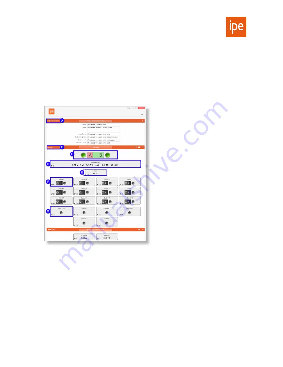
The Overview page is displayed by default when you first log into the IPE Dashboard. It contains the following
collapsible panels:
A.
System Information: Use this to enter details for your entire emu3 system
B.
Device Status: One panel for every currently connected Master/Slave unit; title displays unit name (if configured)
and hardware version (v1 or v2)
Each Device Status panel has the following features:
C.
ACO status and control (
emu3ACO only
): Shows which internal supplies are active and enabled. Click to change
over between supplies (or press the
C/O
button on the front panel).
D.
Power Meter:
–
v1 hardware: Displays the current draw for this unit
–
v2 hardware: Displays current draw, power, voltage, VA, power factor and frequency
E.
Sensor status: One indicator for each sensor connected to this unit (can be up to four)
F.
Power Outlet control: One for each of the 12 outlets on the rear of the unit. Displays the current status. Click on
the
OI
switch to toggle the outlet on or off.
G.
GPI status: Displays the current status of the GPI signal on each of the
GPI 1-6
inputs.
Note:
If a slave unit is offline, its Device Status panel will be greyed out. If there is an overcurrent issue, the Device
Status panel will be highlighted in yellow (warning state) or red (countdown or tripped states). See pages page 24
and page 25.


