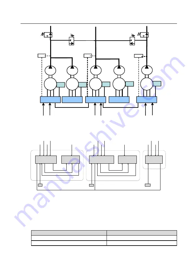
MH860 series hydraulic servo drive
Multi-pump combined flow control
84
Pressure sensor
Pressure sensor
Pressure
sensor
M1
P
Control unit
E/C
M2
Following unit
M3
M4
M5
Independent
unit
CAN
CAN
Slave
node
Slave
node
Master
node
Slave
node
Oil outlet 2
Oil outlet 1
Oil outlet 3
P
P
P
P
E/C
E/C
E/C
E/C
F
lo
w
re
fe
re
n
c
e
F
lo
w
re
fe
re
n
c
e
F
lo
w
re
fe
re
n
c
e
P
re
s
s
u
re
re
fe
re
n
c
e
P
re
s
s
u
re
re
fe
re
n
c
e
P
re
s
s
u
re
re
fe
re
n
c
e
Following unit
Control unit
Hybrid and multi-mode wiring diagram:
Control unit
Following unit
Control unit
Following unit
Single unit
AIN1 AIN2
AOUT2 AOUT1
S_RDY
I7
AIN1 AIN2
AOUT2 AOUT1
S_RDY
I7
Slave node
Master node
Slave node
PT
PT
PT
CAN
CAN
CAN
P2
Q2
C/D
S/ON
P1
Q1
C/D
S/ON
P3
Q3
C/D
S/ON
S/ON
S/ON
PT: Pressure sensor
Q1-3: Flow reference
P1-3: Pressure reference
C/D: Flow combining
selection
S/ON: Drive enabling
I7: DI 7
AIN1 AIN2: Inputs of analog
references 1 and 2
AOUT1 AOUT2: AO1 and AO2
S_RDY: Servo ready
7.5 Communication with two models
In this mode, there is one master node (single-pump system), and multiple slave nodes (of
which each is also a single-pump system). The master node controls which slave nodes
combine flow through the flow splitting/combining selection terminal. There are two types of
node combination.
Flow splitting/combining selection
CAN slave node address selection
Low
CAN slave-node address 1
High
CAN slave-node address 2
P34 (CAN slave-node address 1) and P35 (CAN slave-node address 2): used to select a


