17
Acoustic Interface
Module Installation
The black box that came with your PC/View is called
the Acoustic Interface Module. It houses the trans-
mitters and receivers that communicate with the
transducers. The Acoustic Interface Module must be
connected to the parallel port of the on-board com-
puter, to the transducers and to a source of 12 VDC
power.
1)
Select a location to mount the Acoustic Interface
Module. Keep in mind that the unit must be
protected from from moisture and extreme tem-
peratures. Also, you will need to route the 10’
computer parallel cable, the power cord and
transducer cables to the location that you
choose.
2)
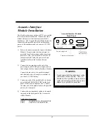
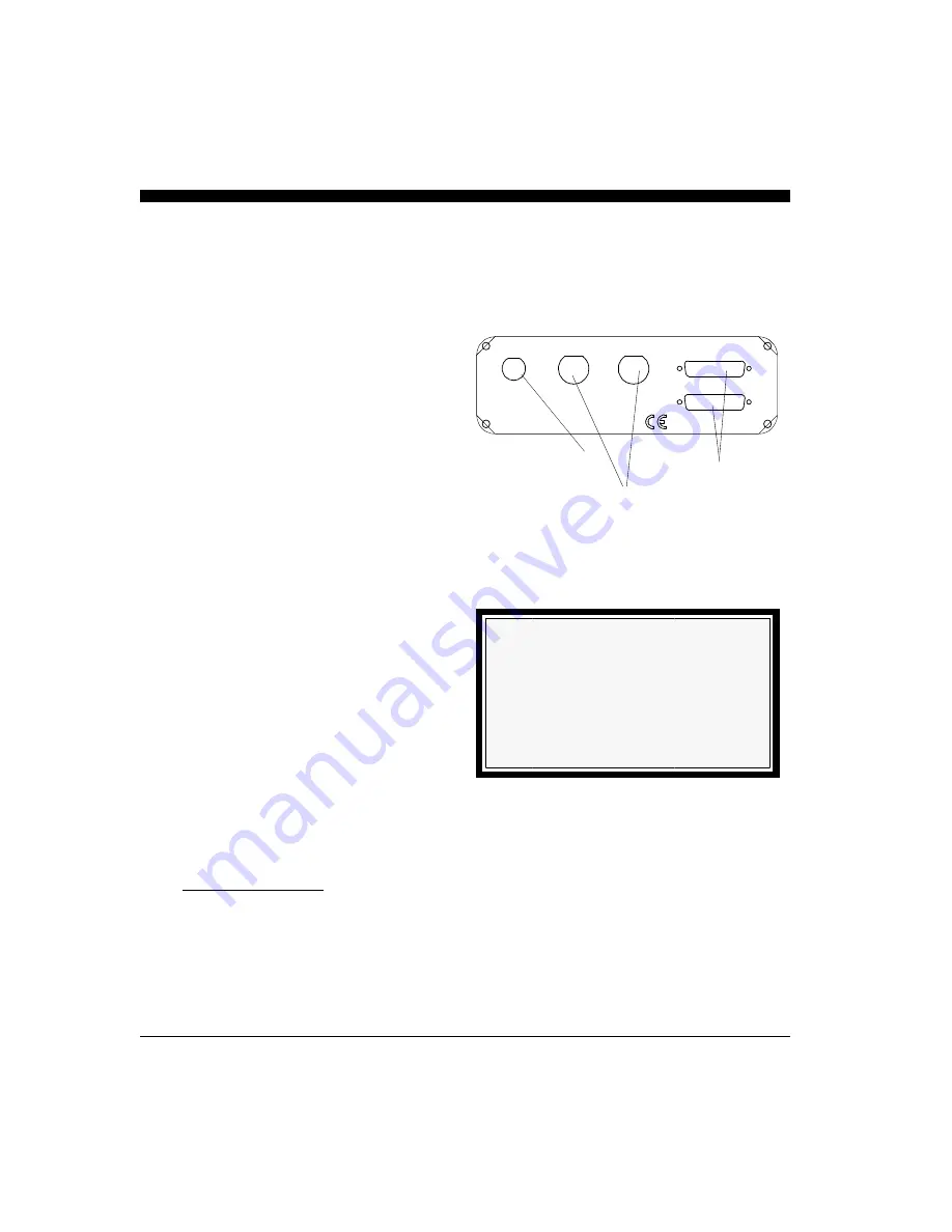
Connect the two-pin plug on the end of the
power supply cable to the power supply jack on
the back panel of the Acoustic Interface Module.
Connect the red wire to the positive terminal
and the black wire to the negative terminal of
your boat’s 12 VDC battery.
3)
Connect one end of the parallel cable to the con-
nector labeled PARALLEL PORT on the back
panel of the Acoustic Interface Unit. Connect
the other end of the parallel cable to the parallel
port on your computer.
4)
Connect the two transducer cables to the match-
ing ports on the back panel of the Acoustic In-
terface Module:
Cable label
Panel label
HORZ
HORZIZONTAL TRANSDUCER
VERT
VERTICAL TRANSDUCER
WARNING
Signals transmitted through adjacent cables
can interfere with one another. Thus, it is
advisable, where possible, to route sensitive
cables and antennas so that they do not run
adjacent to or parallel to one another.
PARALLEL PORT
12 VDC
1 AMP
P/N X1-VIEW-WIN
made in Santa Cruz, CA, USA
Power Supply Jack
Transducer Connectors
Parallel Ports
(use either one)
Acoustic Interface Module
Back Panel
HORIZONTAL
TRANSDUCER
VERTICAL
TRANSDUCER
Содержание PC/View
Страница 1: ...INTERPHASE INTERPHASE PC VIEW for Windows OPERATION MANUAL...
Страница 54: ...54 W Warranty 6 7 55 Z Zoom 33...
Страница 56: ...56...

