


SERVICE AND TECHNICAL SUPPORT MANUAL
Gas Furnace: (F/G)9MXT
Specifications subject to change without notice.
440 04 4321 02
24
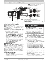
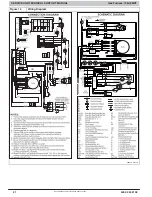
Sequence of Operation
NOTE
: Furnace control must be grounded for proper operation
or control will lockout. Control is grounded through green wire
connected to gas valve and burner bracket screw. Using the
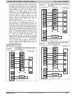
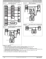
schematic diagram in
Figure 15
, follow the sequence of
operation through the different modes. Read and follow the
wiring diagram very carefully.
NOTE
: If a power interruption occurs during a call for heat
(W/W1 or W/W1andW2), the control will run the blower for
the selected heat offdelay period two seconds after power is
restored, if the thermostat is still calling for gas heating. The
green LED light will flash a status code 1+2 during this period,
after which the LED will switch to a heartbeat, as long as no
faults are detected. After this period, the furnace will respond to
the thermostat normally.
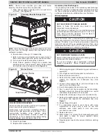
The blower door must be installed for power to be conducted
through the blower door interlock switch ILK to the furnace
control CPU, transformer TRAN, inducer motor IDM, blower
motor BLWM, hotsurface igniter HSI, and gas valve GV.
TwoStage Heating with SingleStage Thermostat
NOTE
: The thermostat type switch (TT) selects either the
twostage thermostat operation mode when ON, (see item 2)
or the single stage thermostat operation mode when OFF in
response to a call for heat. When the W2 thermostat terminal is
energized it will always cause highheat operation when the R
to W circuit is closed, regardless of the setting of the thermostat
type switch. This furnace can operate as a twostage furnace
with a singlestage thermostat because the furnace control
CPU includes a programmed sequence of controlled operation,
which selects lowheat for the first 12 minutes of operation then
switches to high heat operation.
If the power is interrupted, the control CPU will operate in low
heat for 12 minutes then it will switch to highheat, as long as
the thermostat continues to call for heat.
The wall thermostat “calls for heat”, closing the R to W circuit.
The furnace control performs a selfcheck, verifies the
lowheat and highheat pressure switch contacts LPS and
HPS are open, and starts the inducer motor IDM in
highspeed. The HUM terminal is energized for a 115V
humidifier (if used).
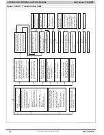
a. Inducer Prepurge Period (see
Figure 15
schematic
diagram)
(1.) Low heat (W/W1) the inducer motor IDM comes up
to highspeed, the lowheat pressure switch LPS
closes. After the lowheat pressure switch closes
the furnace control CPU will begin a 15second
prepurge period, and continue to run the inducer
motor IDM at highspeed.
(2.) High Heat (W/W1+W2) the inducer motor IDM
comes up to high speed and the highheat
pressure switch relay HPSR is deenergized to
close the NC contact. When sufficient pressure is
available, the highheat pressure switch HPS
closes, and the highheat gas valve solenoid
GVHI is energized. After LPS closes, 24VAC
power is supplied for a fieldinstalled humidifier at
the HUM 24VAC terminal and the furnace control
CPU begins a 15second prepurge period. If the
highheat pressure switch HPS fails to close and
the lowheat pressure switch LPS closes, the
furnace will operate at lowheat gas flow rate until
the highheat pressure switch closes for a
maximum of 2 minutes after ignition. If HPS doesn’t
close after 2 minutes from LPS closing, GV is turned
off and heat off delay is completed. Then a new
cycle will begin if a call for heat remains.
b.
Igniter WarmUp
At the end of the prepurge period,
the (Hot Surface Igniter) HSI is energized for a
17second igniter warmup period.
c.
TrialforIgnition Sequence
When the igniter
warmup period is completed the main gas valve relay
contacts GVR close to energize the gas valve solenoid
GVM, the gas valve opens. The gas valve solenoid
GVM permits gas flow to the burners where it is ignited
by the HSI. 5 sec after the GVR closes, a 2sec flame
proving period begins. The HSI igniter will remain
energized until the flame is sensed or until the 2sec
flame proving period begins. If the furnace control CPU
operates in highheat operation, the highheat gas
valve solenoid GVHI is also energized.
d.
FlameProving
When the burner flame is proved at
the flameproving sensor electrode FSE, the inducer
motor IDM switches to lowspeed unless running at
highheat, and the furnace control CPU begins the
blowerON delay period and continues to hold the gas
valve GVM open. If the burner flame is not proved
within two seconds, the control CPU will close the gas
valve GVM, and the control CPU will repeat the ignition
sequence for up to three more TrialsForIgnition
before going to Ignition Lockout. Lockout will be reset
automatically after three hours, or by momentarily
interrupting 115 vac power to the furnace, or by
interrupting 24 vac power at 24VAC or COM to the
furnace control CPU (not at W/W1, G, R, etc.). If flame
is proved when flame should not be present, the furnace
control CPU will lock out of GasHeating mode and
operate the inducer motor IDM on high speed until flame
is no longer proved.
e.
Blower On Delay
If the burner flame is proven, the
blower on delay for lowheat and highheat are as
follows:
LowHeat
45 seconds after the gas valve GVM is
energized the blower motor (BLWM) is energized at LO
HEAT speed.
HighHeat
25 seconds after the gas valve GVM is
energized the BLWM is energized at HI HEAT speed.
Simultaneously, the electronic air cleaner (EAC 1 AMP)
terminal is energized and remains energized as long as
the BLWM is energized.
f.
Switching from Lowto HighHeat
If the furnace
control CPU switches from lowheat to highheat, the
furnace control CPU will switch the inducer motor IDM
speed from low to high. The highheat pressure switch
relay HPSR is deenergized to close the NC contact.
When sufficient pressure is available the highheat
pressure switch HPS closes, and the highheat gas
valve solenoid GVHI is energized. The blower motor
BLWM will switch to HI HEAT speed 5 seconds after the
furnace control CPU switches from lowheat to
highheat.
g.
Switching from High to LowHeat
The furnace
control CPU will not switch from highheat to lowheat
while the thermostat RtoW circuit is closed when
using a single stage thermostat.
h.
HeatOff Delay
When the thermostat is satisfied, the
R to W circuit is opened, deenergizing the gas valve
GVM, stopping gas flow to the burners, and
deenergizing the humidifier terminal HUM 24VAC. The
inducer motor IDM will remain energized for a
15second postpurge period then turn off, also turning
off HUM for 115V humidifier. The blower motor BLWM
and air cleaner terminal EAC 1 AMP will remain
energized for 90, 120, 150, or 180 seconds (depending
on selection at heatoff delay switches). The furnace
control CPU is factoryset for a 120second heatoff
delay.


