


SERVICE AND TECHNICAL SUPPORT MANUAL
Gas Furnace: (F/G)9MXT
Specifications subject to change without notice.
25
440 04 4321 02
15.
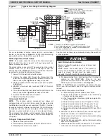
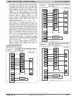
TwoStage Thermostat and TwoStage Heating
(See
Figure 17
Figure 22
for thermostat connections)
NOTE
: In this mode the TT switch (SW11) must be ON to
select the twostage thermostat mode in response to closing
the thermostat RtoW1 circuit. Closing the thermostat
RtoW1andW2 circuits always causes highheat operation,
regardless of the setting of the thermostat type.
The wall thermostat “calls for heat”, closing the RtoW1 circuit
for lowheat or closing the RtoW1 andW2 circuits for
highheat. The furnace control performs a selfcheck, verifies
the lowheat and highheat pressure switch contacts LPS and
HPS are open, and starts the inducer motor IDM in
highspeed.
The start up and shut down functions and delays described in
item 1. above apply to the twostage heating mode as well,
except for switching from low to highheat and vice versa.
a.
Switching from Low to HighHeat
If the thermostat
Rto W1 circuit is closed and the RtoW2 circuit
closes, the furnace control CPU will switch the inducer
motor IDM speed from low to high. The highheat
pressure switch relay HPSR is deenergized to close
the NC contact. When sufficient pressure is available the
highheat pressure switch HPS closes, and the
highheat gas valve solenoid GVHI is energized. The
blower motor BLWM will switch to HI HEAT speed five
seconds after the RtoW2 circuit closes.
b.
Switching from High to LowHeat
If the thermostat
RtoW2 circuit opens, and the RtoW1 circuit
remains closed, the furnace control CPU will switch the
inducer motor IDM speed from high to low. The
highheat pressure switch relay HPSR is energized to
open the NC contact and deenergize the highheat
gas valve solenoid GVHI. When the inducer motor IDM
reduces pressure sufficiently, the highheat pressure
switch HPS will open. The gas valve solenoid GVM will
remain energized as long as the lowheat pressure
switch LPS remains closed. The blower motor BLWM
will switch to LO HEAT speed 5 seconds after the
RtoW2 circuit opens.
16.
Cooling Mode
The thermostat “calls for cooling.”
a.
SingleSpeed Cooling
(See
Figure 17
Figure 22
for thermostat connections)
The thermostat closes the RtoGandY circuits. The
RtoY circuit starts the outdoor unit, and the furnace
control RtoGandY/Y2 circuits start the furnace
blower motor BLWM on cool speed.
The electronic air cleaner terminal EAC 1 AMP is
energized with 115 vac when the blower motor BLWM
is operating.
When the thermostat is satisfied, the RtoG andY
circuits are opened. The outdoor unit will stop, and the
furnace blower motor BLWM will continue operating on
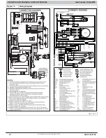
the COOL speed for an additional 90 seconds. Jumper
Y/Y2 to DHUM to reduce the cooling offdelay to 5
seconds. (See
Figure 4
)
b.
TwoSpeed Cooling
The thermostat closes the RtoGandY1 circuits for
lowcooling or closes the RtoGandY1andY2 circuits for
highcooling. The RtoY1 circuit starts the outdoor unit on
lowcooling speed, and the furnace control RtoGandY1
circuit starts the furnace blower motor BLWM on lowcool
speed (same speed as LO HEAT). The RtoY1andY2
circuits start the outdoor unit on highcooling speed, and the
furnace control RtoGandY1 and Y2 circuits start the
furnace blower motor BLWM on COOL speed. The electronic
air cleaner terminal EAC 1 AMP is energized with 115 vac
whenever the blower motor BLWM is operating. When the
thermostat is satisfied, the RtoGandY1 or
RtoGandY1andY2 circuits are opened. The outdoor unit
stops, and the furnace blower BLWM and electronic air cleaner
terminal EAC 1 AMP will remain energized for an additional 90
seconds. Jumper Y1 to DHUM to reduce the cooling offdelay
to 5 seconds. (See
Figure 4
)
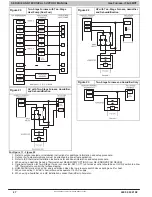
17.
Dehumidify Mode
(See
Figure 17
Figure 22
for humidity sensing
thermostat connections) The dehumidification output, H
on the humidity sensing thermostat should be connected
to the furnace control thermostat terminal DHUM. When
there is a dehumidify demand, the DHUM input is
activated, (24 vac signal is removed from the H input
terminal). In other words, the DHUM input logic is
reversed. The DHUM input is turned ON when no
dehumidify demand exists.
Activation/Deactivation
Once 24 vac is detected by the furnace control on the
DHUM input, the furnace control operates enables the
dehumidify mode. If the DHUM input is off for more than
48 hours, the furnace control disables the dehumidify
mode.
The cooling operation described in item 3. above also
applies to operation with a humidity sensing thermostat.
The exceptions are listed below:
a. Low cooling When the RtoGandY1 circuit is
closed and there is a demand for dehumidification,the
furnace blower motor BLWM will continue running at
lowcool speed (same speed as LO HEAT).
b. High cooling When the RtoGandY/Y2 circuit is
closed and there is a demand for dehumidification,the
furnace blower motor BLWM will drop the blower speed
from COOL to HI HEAT for a maximum of 10 minutes
before reverting back to COOL speed. If there is still a
demand for dehumidification after 20 minutes, the
furnace control CPU will drop the blower speed back to
HI HEAT speed. This alternating 10minute cycle will
continue as long as there is a call for cooling.
c. Cooling offdelay When the “call for cooling” is
satisfied and there is a demand for dehumidification, the
cooling bloweroff delay is decreased from 90 seconds
to 5 seconds.
18.
Continuous Blower Mode
When the RtoG circuit is closed by the thermostat, the
blower motor BLWM will operate on continuousblower
speed LO HEAT speed. Terminal EAC 1 AMP is
energized as long as the blower motor BLWM is
energized. During a call for heat, the blower BLWM will
stop during igniter warmup (17 seconds), ignition (7
seconds), and blowerON delay (45 seconds in
lowheat, and 25 seconds in highheat), allowing the
furnace heat exchangers to heat up more quickly, then
restarts at the end of the blowerON delay period at LO
HEAT or HI HEAT speed respectively. The blower motor
BLWM will revert to continuousblower speed after the
heating cycle is completed. In highheat, the furnace
control CPU will hold the blower motor BLWM at HI HEAT
speed during the selected blowerOFF delay period
before reverting to continuousblower speed.
When the thermostat “calls for lowcooling”, the blower
motor BLWM will operate at lowcool speed (same
speed as LO HEAT).
When the thermostat “calls for highcooling”, the blower
motor BLWM will operate at COOL speed. When the
thermostat is satisfied, the blower motor BLWM will
operate an additional 90 seconds on COOL speed
before reverting back to continuousblower speed.
When the RtoG circuit is opened, the blower motor
BLWM will continue operating for an additional 5
seconds, if no other function requires blower motor
BLWM operation.
19.
Heat Pump
(See
Figure 17
Figure 22
for thermostat connections)
When installed with a heat pump, the furnace control
automatically changes the timing sequence to avoid long
blower off times during demand defrost cycles. When the
RtoW/W1andY1 or RtoW/W1andY1andG
circuits are energized the furnace control CPU will switch
to or turn on the blower motor BLWM at lowcool speed


