background image

SERVICE AND TECHNICAL SUPPORT MANUAL

Gas Furnace: (F/G)9MXT

Specifications  subject to change without notice.

440 04 4321 02

15

3. All factory wires can be left connected, but field

thermostat and accessory wiring may need to be
disconnected depending on their length and routing.

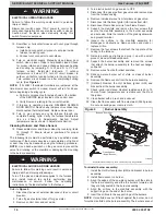
4. If the vent and combustion air pipe passes through the

blower compartment, it will be necessary to remove the
pipes from the blower compartment.

Disconnect the vent  and  combustion air pipe by:

a. Loosen the clamps on the vent couplings and

combustion air pipe external to the furnace.

b. Separate the pipes from the couplings and move

them aside.

c. Loosen the clamps on the vent couplings and

combustion air pipe located on the blower shelf.

d. Separate the pipes from the blower compartment and

set aside.

e. Remove the couplings from the pipe adapters and set

aside.

f. After servicing the blower, reverse steps a through e.

g. Tighten all clamps 15 lbin.
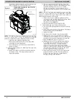
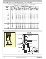
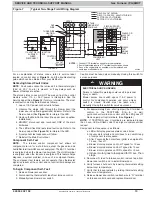
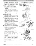
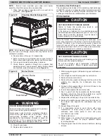
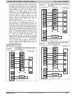
See 

Figure 8

 for steps 5 through 14.

5. Remove screws securing blower assembly to blower

shelf and slide blower assembly out of furnace. Detach
ground wire and disconnect blower motor harness plugs
from blower motor.

NOTE

:  Blower wheel is fragile. Use care.

6. Clean blower wheel and motor by using a vacuum with

soft brush attachment. Be careful not to disturb balance
weights (clips) on blower wheel vanes. Do not bend
wheel or blades as balance will be affected.

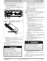
7. If greasy residue is present on blower wheel, remove

wheel from the blower housing and wash it with an
appropriate degreaser. To remove wheel:
a. Mark blower wheel location on shaft before

disassembly to ensure proper reassembly.

b. Loosen setscrew holding blower wheel on motor

shaft.

NOTE

:  Mark blower mounting arms and blower housing so

each arm is positioned at the same hole location during
reassembly.

c. Mark blower wheel orientation and cutoff plate

location to ensure proper reassembly.

d. Remove screws securing cutoff plate and remove

cutoff plate from housing.

e. Remove bolts holding motor mounts to blower

housing and slide motor and mounts out of housing.

f. Remove blower wheel from housing.

g. Clean wheel per instructions on degreaser cleaner.

Do not get degreaser in motor.

8. Torque motor mounting bolts to 40 +/ 10 lbin. when

reassembling.

9. Torque blower wheel set screw to 160 +/ 20 lbin. when

reassembling.

10. Verify that blower wheel is centered in blower housing

and set screw contacts the flat portion of the motor shaft.
Loosen set screw on blower wheel and reposition if
necessary.

11. Spin the blower wheel by hand to verify that the wheel

does not rub on the housing.

12. Reinstall blower assembly in furnace.
13. Reinstall 2 screws securing blower assembly to blower

deck.

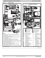
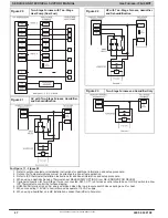
14. Reconnect blower leads to furnace control. Refer to

furnace wiring diagram, and connect thermostat leads if
previously disconnected.

NOTE

:  Be sure to attach ground wire and reconnect blower

harness plugs to blower motor.

Figure 8

Blower Assembly

A11347

Содержание F9MXT0401410A

Страница 1: ...bination with colors and or pictures or product labels The signal word WARNING is used throughout this manual in the following manner Safety alert symbol When you see this symbol on the unit and in instructions or manuals be alert to the potential for personal injury TABLE OF CONTENTS START UP ADJUSTMENT AND SAFETY CHECK 4 THERMOSTAT SETUP SWITCH 4 PRIME CONDENSATE TRAP WITH WATER 4 PURGE GAS LINE...

Страница 2: ...death WARNING signifies hazards which could result in personal injury or death CAUTION is used to identify unsafe practices which may result in minor personal injury or product and property damage NOTE is used to highlight suggestions which will result in enhanced installation reliability or operation WARNING PERSONAL INJURY AND OR PROPERTY DAMAGE HAZARD Failure to carefully read and follow this w...

Страница 3: ...Furnace Drip Leg Gas Valve turned ON Type of Gas Natural Propane Filter Type and Size Shade in Heating Fan Time OFF Setting and Thermostat Type setting ON OFF 1 2 3 TT OFF DLY Calculated Input BTU Rate See Checks and Adjustments Section Heating Check Measured Line Pressure During High Heat Measured Manifold Pressure High Heat Low Heat Temperature of Supply Air High Heat Low Heat Temperature of Ret...

Страница 4: ... thermostat W to W W1 at furnace control terminal block See Figure 7 For single stage thermostats the control will operate for 12 minutes on low heat then switch to high heat if heat call remains Setup switch TT must be in the factory shipped OFF position See Figure 7 and Figure 15 for setup switch information If a two stage heating thermostat is to be used move setup switch TT to ON position befo...

Страница 5: ... heat value and specific gravity lines to point of intersection to find orifice size and low and high heat manifold pressure settings for proper operation f Check and verify burner orifice size in furnace NEVER ASSUME ORIFICE SIZE ALWAYS CHECK AND VERIFY Table 1 Altitude Derate Multiplier for U S A ALTITUDE FT M PERCENT OF DERATE DERATE MULTIPLIER FACTOR 0 2000 0 610 0 1 00 2001 3000 610 914 4 6 0...

Страница 6: ...o increase input rate NOTE DO NOT set high heat manifold pressure less than 3 2 in w c or more than 3 8 in w c for natural gas If manifold pressure is outside this range change main burner orifices to obtain manifold pressure in this range c When correct input is obtained replace caps that conceal gas valve regulator adjustment screws Main burner flame should be clear blue almost transparent See F...

Страница 7: ...3 8 1 6 42 3 2 1 4 850 44 3 8 1 6 43 3 5 1 5 43 3 6 1 5 43 3 7 1 6 875 44 3 6 1 5 44 3 7 1 6 43 3 4 1 4 43 3 5 1 5 4000 900 44 3 4 1 4 44 3 5 1 5 44 3 7 1 5 44 3 8 1 6 1219 925 44 3 2 1 4 44 3 4 1 4 44 3 5 1 5 44 3 6 1 5 950 45 3 7 1 6 44 3 2 1 3 44 3 3 1 4 44 3 4 1 4 750 42 3 3 1 4 42 3 4 1 4 42 3 5 1 5 42 3 6 1 5 4001 775 43 3 7 1 6 43 3 8 1 6 42 3 3 1 4 42 3 4 1 4 1220 800 43 3 5 1 5 43 3 6 1 5...

Страница 8: ... 1 6 9000 750 44 3 3 1 4 44 3 4 1 4 44 3 5 1 5 44 3 6 1 5 2743 775 45 3 7 1 6 44 3 2 1 3 44 3 3 1 4 44 3 4 1 4 9001 600 42 3 3 1 4 42 3 4 1 5 42 3 6 1 5 42 3 7 1 6 2744 625 43 3 7 1 6 42 3 2 1 3 42 3 3 1 4 42 3 4 1 4 650 43 3 5 1 5 43 3 6 1 5 43 3 7 1 6 43 3 8 1 6 675 44 3 7 1 6 44 3 8 1 6 43 3 4 1 4 43 3 5 1 5 10000 700 44 3 4 1 4 44 3 5 1 5 44 3 7 1 5 44 3 8 1 6 3048 725 44 3 2 1 3 44 3 3 1 4 44...

Страница 9: ...pply ducts for excessive restrictions causing static pressures greater than 0 50 in w c d Adjust temperature rise by adjusting blower speed e Increase blower speed to reduce temperature rise f Decrease blower speed to increase temperature rise ELECTRICAL OPERATION HAZARD Failure to follow this warning could result in personal injury or death Disconnect 115V electrical power before changing speed t...

Страница 10: ...otor if furnace overheats By using this method to check limit control it can be established that limit is functioning properly and will operate if there is a restricted return air supply or motor failure If limit control does not function during this test cause must be determined and corrected a Run furnace for at least 5 minutes b Gradually block off return air with a piece of cardboard or sheet ...

Страница 11: ... 375 120 30 60 150 49 73 147 367 Table 6 AIR DELIVERY CFM with filter INPUT BTUH RETURN AIR SUPPLY SPEED EXTERNAL STATIC PRESSURE in w c 0 1 0 2 0 3 0 4 0 5 0 6 0 7 0 8 0 9 1 40 000 SIDE BOTTOM 5 Gry 1120 1080 1030 980 925 875 820 760 690 630 4 Yel 880 845 810 780 740 710 680 640 615 570 3 Blu 695 665 620 575 535 495 455 420 370 280 2 Org 640 595 540 495 460 420 370 310 260 230 1 Red 570 525 475 4...

Страница 12: ...n to component location accordingly Figure 6 Multipoise Orientations A93041 Electrical Controls and Wiring ELECTRICAL SHOCK HAZARD Failure to follow this warning could result in personal injury or death There may be more than one electrical supply to the furnace Check accessories and cooling unit for additional electrical supplies that must be shut off during furnace servicing Lock out and tag swi...

Страница 13: ...urnace control component test allows all components to run for a short time except the gas valve and humidifier terminal HUM are not energized The EAC 1 terminal is energized when the blower is energized The HUM terminal is energized when the inducer is energized This feature helps diagnose a system problem in case of a component failure The component test feature will not operate if any thermosta...

Страница 14: ... necessary 4 Inspect burner compartment before each heating season for rust corrosion soot or excessive dust If necessary have furnace and burner serviced by a qualified service agency 5 Inspect the vent pipe vent system before each heating season for water leakage sagging pipes or broken fittings Have vent pipes vent system serviced by a qualified service agency 6 Inspect any accessories attached...

Страница 15: ... balance will be affected 7 If greasy residue is present on blower wheel remove wheel from the blower housing and wash it with an appropriate degreaser To remove wheel a Mark blower wheel location on shaft before disassembly to ensure proper reassembly b Loosen setscrew holding blower wheel on motor shaft NOTE Mark blower mounting arms and blower housing so each arm is positioned at the same hole ...

Страница 16: ...mage Turn off the gas and electrical supplies to the furnace and install lockout tag before performing any maintenance or service Follow the operating instructions on the label attached to the furnace WARNING Refer to Figure 9 1 Disconnect power at external disconnect fuse or circuit breaker 2 Turn off gas at external shut off or gas meter 3 Remove control door and set aside 4 Turn electric switch...

Страница 17: ...e Servicing Hot Surface Igniter The igniter does NOT require annual inspection Check igniter resistance before removal Refer to Figure 9 Figure 10 and Figure 11 1 Turn off gas and electrical supplies to furnace 2 Remove control door 3 Disconnect igniter wire connection 4 Check igniter resistance Igniter resistance is affected by temperature Only check resistance when the igniter is at room tempera...

Страница 18: ...ach the relief hose to the relief port on the condensate trap and collector box 5 Secure tubing to prevent any sags or traps in the tubing 6 Connect condensate drain elbow or drain extension elbow to the condensate trap 7 Connect the leads of the condensate heat pad if used 8 Connect external drain piping to the condensate drain elbow or drain extension pipe 9 Turn gas on at electric switch on gas...

Страница 19: ...amage If the furnace is installed in an unconditioned space where the ambient temperatures may be 32_ F 0_ C or lower freeze protection measures must be taken to prevent property or product damage CAUTION Since the furnace uses a condensing heat exchanger some water will accumulate in the unit as a result of the heat transfer process Therefore once it has been operated it cannot be turned off and ...

Страница 20: ...SERVICE AND TECHNICAL SUPPORT MANUAL Gas Furnace F G 9MXT Specifications subject to change without notice 440 04 4321 02 20 Figure 14 Service Label 338313 2E ...

Страница 21: ...SERVICE AND TECHNICAL SUPPORT MANUAL Gas Furnace F G 9MXT Specifications subject to change without notice 21 440 04 4321 02 Figure 15 Wiring Diagram 338313 2 Rev E ...

Страница 22: ...be turned on Inducer motor will start in HIGH speed and remain on HIGH until the end of the blower test then shift to LOW speed for 7 to 15 seconds the following components are on for 10 15 seconds each individually hot surface igniter blower speeds LO HEAT HI HEAT COOL Was there a previous status code Go to section below for the flashed status code Does the control respond to W W1 W2 Y1 Y Y2 and ...

Страница 23: ...K check burner carryover and flame sensor location Clean flame sensor with fine steel wool and recheck current Nominal current is 4 0 to 6 0 A DC Is current near typical value Replace electrode Will main burners ignite and stay on Replace furnace control Fixed YES YES NO NO Replace furnace control Check for continuity in the harness and igniter Replace defective component Reconnect the R thermosta...

Страница 24: ...utes after ignition If HPS doesn t close after 2 minutes from LPS closing GV is turned off and heat off delay is completed Then a new cycle will begin if a call for heat remains b Igniter Warm Up At the end of the prepurge period the Hot Surface Igniter HSI is energized for a 17 second igniter warm up period c Trial for Ignition Sequence When the igniter warm up period is completed the main gas va...

Страница 25: ... and Y1 or R to G and Y1 and Y2circuits are opened The outdoor unit stops and the furnace blower BLWM and electronic air cleaner terminal EAC 1 AMP will remain energized for an additional 90 seconds Jumper Y1 to DHUM to reduce the cooling off delay to 5 seconds See Figure 4 17 Dehumidify Mode See Figure 17 Figure 22 for humidity sensing thermostat connections The dehumidification output H on the h...

Страница 26: ...and Y Y2 and G circuits are energized the furnace control CPU will switch to or turn on the blower motor BLWM at COOL speed and begin a high heat cycle The blower motor BLWM will remain on until the end of the prepurge period then shut off for 24 seconds then come back on at HI HEAT speed When the W W1 input signal disappears the furnace control begins a normal inducer post purge period and the bl...

Страница 27: ...re 2 Outdoor Air Temperature Sensor must be attached in all dual fuel application 3 Refer to ICP thermostat Installation Instructions for additional information and setup procedure 4 When using a Humidity Sensing Thermostat set DEHUMIDIFY OPTIONS to H DE ENRGZD FOR DEHUM 5 Optional connection for Two Stage If wire is connected SW1 1 TT on furnace control should be set to ON position to allow ICP T...

Страница 28: ...e when used Inducer motor capacitor when used Collector box Condensate trap Condensate trap elbow Gaskets WARNING FIRE EXPLOSION ELECTRICAL SHOCK AND CARBON MONOXIDE POISONING HAZARD Failure to follow this warning could result in dangerous operation personal injury death or property damage Improper installation adjustment alteration service maintenance or use can cause carbon monoxide poisoning ex...

Страница 29: ...T Two stage FEATURE B Base AFUE Efficiency E Extra AFUE Efficiency C Communicating D Dual Certified 2 pipe or 1 pipe R 2 pipe only S Single stage T Two stage N Standard L Low Nox FEATURE 040 40 000 BTU hr 060 60 000 BTU hr 080 80 000 BTU hr 100 100 000 BTU hr 120 120 000 BTU hr INPUT HEAT 14 14 3 16 17 17 1 2 21 21 24 24 1 2 CABINET WIDTH 10 1000 CFM max 14 1400 CFM max 16 1600 CFM max 20 2000 CFM...

Отзывы: