Intepro systems PS 9080-100 1U Скачать руководство пользователя страница 47

47

PS 9000 1U Series

PS 9000 1U Series  •  DC Laboratory Power Supply  •  User Manual

3.9.1.5  Alarms and other problem situations

Parallel operation, because of the connection of multiple units and their interaction, can cause additional problem 

situations which do not occur when operating individual units. For such occurrences the following regulations have 

been defined:

• 

If one or more slave units are switched off on the AC side (power switch, supply undervoltage) and come back 

later, they’re automatically included again in the system. The remaining units will continue to work without inter-

ruption, but the entire system will provide less power

• 

If the DC output of the master unit is switched off because of a defect or overheating, then the total parallel 

system can provide no output power

• 

If accidentally multiple or no units are defined as master the Share Bus parallel system cannot be initialized

In situations where one or multiple units generate a device alarm like OV, PF or OT following applies:

• 

Any alarm of a slave is indicated on the slave’s display only

3.9.2  Series connection

Series connection of two or multiple devices is possible. But for reasons of safety and isolation, some restrictions 

apply:

• 

Both, negative (DC-) and positive (DC+) output poles, are coupled to PE via type X capacitors

• 

None DC minus pole of any unit in the series connection must have a potential of >400 V 

against ground (PE)!

• 

The Share Bus must not be wired and used!

• 

Remote sensing must not be used!

• 

Series connection is only allowed with devices of the same kind and model, i.e. power supply 

with power supply, like for example PS 9080-100 1U with PS 9080-100 1U or similar models 

like PS/PSI 9080-120 2U

Series connection is not supported by the software and hardware of the device. It means, all units have to controlled 

separately regarding set values and DC output status, whether it is manual control or digital remote control. In 

remote control, an almost synchronous control can be achieved by using the Ethernet ports and sending message 

as broadcast, so they address multiple units at once.
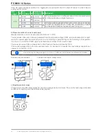
The figure below depicts the exemplary series connection of three identical devices with 200 V nominal output 

voltage and the maximum potential shift of any DC- output against PE:

3.9.3  Operation as battery charger

A power supply can be used as a battery charger, but with some restrictions, because it misses a battery supervi-

sion and a physical separation from the load in form of a relay or contactor, which is featured with some real battery 

chargers as a protection.
The following have to be considered:

• 

No false polarity protection inside! Connecting a battery with false polarity will damage the power supply severely, 

even if it is not powered.

• 

All models of this series have an internal circuit, i.e. base load, for faster discharge of voltage when switching the 

DC output off or ramping voltage down. This base load would, more or less slowly, discharge the battery while 

the DC output is switched off, means while it is not charging. This would, however, not occur when the power 

supply is not powered at all. It is thus recommended to leave the DC output switched on as long as the battery 

is connected (equals to trickle charge) and only switch if off for connecting/disconnecting a battery.

Содержание PS 9080-100 1U

Страница 1: ...THE POWER TEST EXPERTS User Manual Attention This document is only valid for devices with firmware KE 2 07 and HMI 2 03 or higher For availability of updates for your device check our website or cont...

Страница 2: ......

Страница 3: ...ting the USB port 26 2 3 11 Initial commission 26 2 3 12 Initial network setup 27 2 3 13 Commission after a firmware update or a long period of non use 27 3 OPERATIONANDAPPLICATION 3 1 Important notes...

Страница 4: ...tepro Systems LP Specifications subject to change without notice 4 3 Calibration readjustment 51 4 3 1 Preface 51 4 3 1 1 Preparation 51 4 3 2 Calibration procedure 51 5 CONTACTAND SUPPORT 5 1 General...

Страница 5: ...document 1 1 4 Explanation of symbols Warning and safety notices as well as general notices in this document are shown in a box with a symbol as follows Symbol for a life threatening danger Symbol for...

Страница 6: ...of the device in Volt Series 8 Series 8000 or 800 9 Series 9000 Type identification PS Power Supply usually programmable PSI Power Supply Intelligent always programmable ELR Electronic Load with Reco...

Страница 7: ...equipment and to the source ESD regulations must be applied when plugging interface cards or modules into the relative slot Interface cards or modules may only be attached or removed after the device...

Страница 8: ...cleaning of the equipment ensure that all employees who use the equipment have read and understood the manual Furthermore the users are to be regularly schooled in working with the equipment and the...

Страница 9: ...hold was lower than the actual output voltage Critical The device and or the load could be damaged Signal OCP OverCurrent Shutdown of the DC output due to excess of the preset limit Non critical prote...

Страница 10: ...1 7 ms 1 4 ms 2 2 ms 2 ms 2 ms Display Resolution See section 1 9 4 4 Resolution of the displayed values Display Accuracy 3 0 2 UNom 0 2 UNom 0 2 UNom 0 2 UNom 0 2 UNom Ripple 2 100 mVPP 5 2 mVRMS 29...

Страница 11: ...1150 V DC Miscellaneous Cooling Temperature controlled fans front inlet rear exhaust Ambient temperature 0 50 C Storage temperature 20 70 C Humidity 80 not condensing Standards EN 61010 EN 61326 Overv...

Страница 12: ...s 2 2 ms 2 ms 2 ms Display Resolution See section 1 9 4 4 Resolution of the displayed values Display Accuracy 3 0 2 UNom 0 2 UNom 0 2 UNom Ripple 2 76 mVPP 4 2 mVRMS 234 mVPP 40 mVRMS 156 mVPP 26 mVRM...

Страница 13: ...V DC 1150 V DC Miscellaneous Cooling Temperature controlled fans front inlet rear exhaust Ambient temperature 0 50 C Storage temperature 20 70 C Humidity 80 not condensing Standards EN 61010 EN 61326...

Страница 14: ...cifications subject to change without notice Figure 1 Front side Figure 2 Rear side 1 8 4 Views A Mains switch D Exhausts G AC input connector B Control panel E Share Bus and remote sensing connectors...

Страница 15: ...15 PS 9000 1U Series PS 9000 1U Series DC Laboratory Power Supply User Manual Figure 3 Left hand side view with DC cover Figure 4 Right hand side view without DC cover...

Страница 16: ...16 PS 9000 1U Series 2015 Intepro Systems LP Specifications subject to change without notice Figure 5 Top view...

Страница 17: ...ubmenus and parameters direction up left or changes view mode Button Navigates through menus submenus and parameters direction down right or changes view mode Button Submits altered parameters or set...

Страница 18: ...to 1500 V DC In addition the devices offer as standard the possibility for parallel connection in Share bus operation for constant current sharing Operating in this way allows up to 10 units to be com...

Страница 19: ...pushing the corresponding rotary knob in order to move the cursor The left hand rotary knob is always assigned to the DC output voltage and related parameters like OVP or U max whereas the right hand...

Страница 20: ...ts The number of decimal places depends on the device model The values have 4 or 5 digits while actual and set values related to the same physical unit always have the same number of digits Adjustment...

Страница 21: ...other reserved ports The standard port for this device is 5025 default IP is 192 168 0 2 Via TCP IP and this port communication to the device can be established in most of the common programming lang...

Страница 22: ...ore commissioning the equipment should be visually inspected for damage and completeness using the delivery note and or parts list see section 1 9 3 Scope of delivery An obviously damaged device e g l...

Страница 23: ...et or multi socket outlet as long as the socket features a safety contact PE and is capable for 16 A When connecting the device to a multi socket outlet along with other electric devices it is importa...

Страница 24: ...erage ambient temperature up to 50 C we recommend up to 10 A 0 75 mm AWG18 up to 15 A 1 5 mm AWG14 up to 30 A 4 mm AWG10 up to 40 A 6 mm AWG8 up to 60 A 16 mm AWG4 up to 100 A 25 mm AWG2 per lead mult...

Страница 25: ...ad The device recognizes the remote sensing mode automati cally and regulates the output voltage only in CV operation at the load rather than at its own DC output In the technical specifications see s...

Страница 26: ...it is strongly recommended to use and install the included driver installer on the USB stick to gain maximum compatibility of the device to our software 2 3 10 2 Driver installation Linux MacOS We ca...

Страница 27: ...P http 192 168 0 2 or the default host name http Client only possible if there is a running DNS in the network into the URL box 3 After the website has been completely loaded check the status field it...

Страница 28: ...output power according to P UOUT IOUT reaches the adjusted current or power limit In both cases the device will automatically change to constant current or constant power operation whichever occurs fi...

Страница 29: ...current according to I P U The adjustable set value of current as indicated in the display is always a upper limit While the DC output is switched on and constant power mode is active then the conditi...

Страница 30: ...witch on again to continue operation 3 3 3 Overvoltage An overvoltage alarm OVP will switch off the DC output and can occur if the power supply itself as a voltage source generates an output voltage h...

Страница 31: ...red 3 4 2 Switching off the device On switch off the last output condition and the most recent set values are saved Furthermore a PF alarm power failure will be reported but can be ignored The DC outp...

Страница 32: ...min ____A I max ____A P max ____W General Calibration Reset Communication IP Settings 2 HMI Setup Language English Deutsch Display Language Brightness 1 10 HMI Lock HMI lock Lock all ON OFF possible E...

Страница 33: ...o switch off DC output after PF alarm 6 Determines how the DC output shall react after a power fail PF alarm has occurred OFF DC output will be switched off and remain until user action AUTO DC output...

Страница 34: ...IP address in standard IP format Subnet mask Only available with setting Get IP address Manual Default value 255 255 255 0 Permanent manual setting of the subnet mask in standard IP format Gateway Onl...

Страница 35: ...e That also includes remote control via analog or digital interface In remote control the global range of 0 100 digital resp 0 5 V 0 10 V remains only narrowed by the limits defined here An example yo...

Страница 36: ...after leaving the setup menu and the right hand rotary knob is then either assigned to set value of current or power 3 4 6 Manual adjustment of set values Adjusting set values of voltage current and p...

Страница 37: ...tput on during manual operation or digital remote control can be disabled by pin REM SB of the built in analog interface For more information refer to 3 4 3 1 and example a in 3 5 4 6 How to manually...

Страница 38: ...via the digital interface is active Remote then remote control is immediately terminated and must be reactivated at the PC once Local is no longer active If remote control is via the analog interface...

Страница 39: ...value outputs CMON VMON Input of excess set values e g 5 V in selected 5 V range or 10 V in the 10 V range are clipped by setting the set value at 100 Before you begin please read Important notes for...

Страница 40: ...5 V correspond to 0 100 von PNom Accuracy 0 5 V range 0 4 Accuracy 0 10 V range 0 2 Input im pedance Ri 40 k 100 k 9 VMON AO Actual voltage 0 10 V or 0 5 V correspond to 0 100 von UNom Accuracy 0 2 at...

Страница 41: ...n 2 03 this is also available without remote control being active It is recommended that a low resistance contact such as a switch relay or transistor is used to switch the pin to ground DGND The foll...

Страница 42: ...ated Pin Remote LOW The set values VSEL and CSEL are generated from the reference voltage VREF using potentiometers for each Hence the power supply can selectively work in current limiting or power li...

Страница 43: ...in REM SB to the level that corresponds to DC output off then switch it on again See section 3 5 4 6 Application examples for levels and logic How to acknowledge an alarm in the alarm buffer status du...

Страница 44: ...between a simple lock and a PIN lock which requires to enter the correct PIN every time someone wants to unlock the HMI How to lock the HMI 1 Switch off the DC output and push button to call the setup...

Страница 45: ...nge in HMI language On calling up the menu page and selecting a profile the most important settings can be seen but not changed How to save the current values and settings work profile as a user profi...

Страница 46: ...cted to the next unit using cables with cross section according to the maximum current and with short as possible length 3 9 1 2 Wiring the Share bus The Share bus is wired from unit to unit with an i...

Страница 47: ...same kind and model i e power supply with power supply like for example PS 9080 100 1U with PS 9080 100 1U or similar models like PS PSI 9080 120 2U Series connection is not supported by the software...

Страница 48: ...ed limits for the application should be set in the power supply This can be done via the interface The electronic load should preferably be in operating mode CV The load will then using the Share Bus...

Страница 49: ...put s of all units switched off In this combination of devices it is recommended to always switch on the DC output of the source first and then the DC input of the sink 1 Discharge of the battery to 2...

Страница 50: ...ipping destination is abroad the necessary customs papers are attached 4 2 1 Replacing a defect mains fuse The device is protected by one fuse T16 A 250 V 35 mm which is located inside the device This...

Страница 51: ...imeter for voltage with a max error of half the PS s voltage error That measure ment device can also be used to measure the shunt voltage when readjusting the current If the current is also going to b...

Страница 52: ...and start to measure the output current I mon Simply confirm here with 4 After this the device requests you to enter the output current which you are measuring with the shunt at Measured value Enter i...

Страница 53: ...4 3 2 2 Actual values Actual values of output voltage with and without remote sensing and output current are calibrated almost the same way as the set values but here you don t need to enter anything...

Страница 54: ...86 sales inteproate com www inteproate com United Kingdom Intepro UK Ltd 9 Lakeside Business Park Swan Lane Sandhurst Berkshire GU47 9DN UK Tel 44 012 5287 5600 China Intepro Power Block 7 Fourth Indu...

Отзывы: