


40
PS 9000 1U Series
© 2015 Intepro Systems, LP. Specifications subject to change without notice.
3.5.4.3
Analog interface specification
Pin Name
Type* Description
Default levels
Electrical properties
1 VSEL
AI
Set voltage value
0…10 V or. 0...5 V corre-
spond to 0..100% of U
Nom
Accuracy 0-5 V range: < 0.4% ****
Accuracy 0-10 V range: < 0.2% ****
Input impedance R
i
>40 k...100 k
2
CSEL
AI
Set current value
0…10 V or. 0...5 V corre-
spond to 0..100% of I
Nom
3 VREF
AO
Reference voltage 10 V or 5 V
Tolerance < 0.2% at I
max
= +5 mA
Short-circuit-proof against AGND
4 DGND
POT Ground for all
digital signals
For control and status signals.
5 REMOTE
DI
Switching internal /
remote control
Remote = LOW, U
Low
<1 V
Internal = HIGH, U
High
>4 V
Internal = Open
Voltage range = 0…30 V
I
Max
= -1 mA bei 5 V
U
LOW to HIGH typ.
= 3 V
Rec’d sender: Open collector against DGND
6
OT
DO
Overheating or
power fail*** alarm
Alarm OT= HIGH, U
High
> 4 V
No Alarm OT= LOW, U
Low
<1
V
Quasi open collector with pull-up against Vcc **
With 5 V on the pin max. flow +1 mA
I
Max
= -10 mA at U
CE
= 0,3 V
U
Max
= 30 V
Short-circuit-proof against DGND
7 -
-
-
-
-
8 PSEL
AI
Set power value
0…10 V or. 0...5 V correspond
to 0..100% von P
Nom
Accuracy 0-5 V range: < 0.4% ****
Accuracy 0-10 V range: < 0.2% ****Input im-
pedance R
i
>40 k...100 k
9
VMON
AO
Actual voltage
0…10 V or. 0...5 V correspond
to 0..100% von U
Nom
Accuracy < 0.2% at I
Max
= +2 mA
Short-circuit-proof against AGND
10 CMON
AO Actual current
0…10 V or. 0...5 V corre-
spond to 0..100% von I
Nom
11 AGND
POT Ground for all
analog signals
For -SEL, -MON, VREF Signals
12 -
-
-
-
-
13 REM-SB
DI
DC output OFF
(DC output ON)
(ACK alarms ****)
Off = LOW, U
Low
<1 V
On= HIGH, U
High
>4 V
On = Open
Voltage range = 0…30 V
I
Max
= +1 mA at 5 V
Rec’d sender: Open collector against DGND
14 OVP
DO
Overvoltage alarm Alarm OV = HIGH, U
High
> 4 V
No alarm OV = LOW, U
Low
<1 V Quasi open collector with pull-up against Vcc **
With 5 V on the pin max. flow +1 mA
I
Max
= -10 mA at U
CE
= 0,3 V, U
Max
= 30 V
Short-circuit-proof against DGND
15 CV
DO
Constant voltage
regulation active
CV = LOW, U
Low
<1 V
CC/CP = HIGH, U
High
>4 V
* AI = Analog Input, AO = Analog Output, DI = Digital Input, DO = Digital Output, POT = Potential
** Internal Vcc approx. 14.3 V *** Mains blackout, mains over- or undervoltage or PFC error **** Only during remote control
The accuracy of set values, as given in the table above, is only related to the input pin and adds
to the general accuracy of the corresponding value on the DC output (see technical specs)
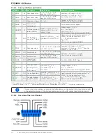
3.5.4.4 Overview of the Sub-D Socket


