Intel
®
Server Chassis P4304XXMFEN2/P4304XXMUXX Product Family System Integration and Service Guide
x
List of Figures
Figure 1. Intel® Server Chassis P4304XXMFEN2 – Fixed Power Supply ............................................................................... 2
Figure 2. Intel® Server Chassis P4304XXMUXX – Optional Redudant Power Supplies .................................................. 2
Figure 3. Server Board Installation ....................................................................................................................................................... 5
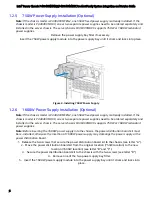
Figure 4. Installing 750W Power Supply ............................................................................................................................................ 6
Figure 5. Installing 1600W Power Supply ......................................................................................................................................... 8
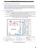
Figure 6. P4304XXMFEN2 Cable Routing .......................................................................................................................................... 9
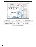
Figure 7. P4304XXMUXX Cable Routing ......................................................................................................................................... 10
Figure 8. Connecting Power Cables ................................................................................................................................................... 11
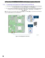
Figure 9. Connecting System Fan Cables ........................................................................................................................................ 12
Figure 10. Internal Cable Routing ....................................................................................................................................................... 16
Figure 11. System Fan Assembly Removal ..................................................................................................................................... 20
Figure 12. System Fan Assembly Installation ............................................................................................................................... 22
Figure 13. Processor Heatsink Removal .......................................................................................................................................... 24
Figure 14. Processor Installation – Open the Socket Lever .................................................................................................... 25
Figure 15. Processor Installation– Open the Load Plate .......................................................................................................... 25
Figure 16. Processor Installation – Install the Processor ......................................................................................................... 26
Figure 17. Processor Installation – Remove the Socket Cover .............................................................................................. 26
Figure 18. Processor Installation – Close the Load Plate ......................................................................................................... 27
Figure 19. Processor Installation – Latch the Locking Lever ................................................................................................... 27
Figure 20. Processor Heatsink Installation ..................................................................................................................................... 28
Figure 21. Installing Memory ................................................................................................................................................................ 29
Figure 22. Removing Memory .............................................................................................................................................................. 30
Figure 23. Installing Hot-swap Storage Devices – 3.5” Carrier Extraction ......................................................................... 54
Figure 24. 3.5” Hard Disk Drive Installation – Removing the Drive Blank .......................................................................... 54
Figure 25. 3.5” Hard Disk Drive Installation – Mounting the Drive to the Carrier ........................................................... 55
Figure 26. Option to Install a 2.5” SSD into a 3.5” Carrier ........................................................................................................ 55
Figure 27. Hard Disk Drive Installation – Inserting the 3.5” HDD Assembly ..................................................................... 56
Figure 28. Installing Hot-swap Storage Devices – 2.5” Carrier Extraction ......................................................................... 57
Figure 29. 2.5” Storage Device Installation – Removing the Drive Blank ........................................................................... 57
Figure 30. 2.5” Storage Device Installation – Mounting the Drive to the Carrier ............................................................ 58
Figure 31. 2.5” Storage Device Installation – Inserting the 2.5” Drive Assembly ........................................................... 58
Figure 32. Removing the EMI Shield ................................................................................................................................................. 60
Figure 33. Installing the Optical Drive .............................................................................................................................................. 60
Figure 34. Removing the Optical Drive ............................................................................................................................................ 61
Figure 35. Re-inserting the Empty EMI Shield .............................................................................................................................. 61
Figure 36. ESRT2 RAID 5 Key Location ............................................................................................................................................ 62
Figure 37. IMR RAID 5 Key Location .................................................................................................................................................. 63
Figure 38. BBU Unit Connection to the RAID card ...................................................................................................................... 64


